
An AC surge protective device (SPD) is the component standing between the utility supply and everything a facility depends on: PLCs, VFDs, metering, servers, and control panels. This guide is written by the Britec Electric engineering team — Wenzhou Britec Electric Co., Ltd. has manufactured surge protective devices in Zhejiang, China since 2003 under an ISO 9001 quality system, with TUV, CE, and Intertek SEMKO certified product lines — and it focuses specifically on the failure mechanisms of low-voltage AC power systems and the engineering solutions that fix them.
Most published failure advice treats every SPD the same, whether it is mounted on a 230/400 V AC distribution board or a 1500 V DC string. That is misleading. An AC SPD lives in a fundamentally different electrical environment: it sees a continuously cycling 50/60 Hz waveform, temporary overvoltages caused by neutral loss and line faults, power-frequency follow current after every discharge, and harmonics injected by the very loads it protects. Those mechanisms produce failures that a generic checklist will never catch.
If you want a broader taxonomy that also covers installation and environmental causes, start with our guide to common SPD surge protective device failure causes and solutions. This article goes one level deeper into the AC-specific physics — and every section below ends with the practical fix we recommend to B2B buyers and panel builders.
A metal-oxide varistor (MOV) inside an AC SPD is never truly at rest. Even when no surge is present, the varistor sits across a 230 V phase-to-neutral supply and draws a small leakage current around every voltage peak. The device is therefore not a passive spare part: it is a component under permanent electrical stress, and its failure mode is shaped by everything the supply does between lightning events.
That stress profile is why AC SPDs almost never fail the way DC SPDs do. On an AC system the voltage crosses zero 100 or 120 times per second, which gives arresters and spark gaps a natural opportunity to extinguish follow current. On the other hand, AC systems generate sustained overvoltages — a lost neutral, a broken PEN conductor, a mis-set transformer tap — that can hold an elevated voltage across the varistor for seconds or hours. Understanding this asymmetry is the key to diagnosing AC failures quickly, and each of the six causes below is a direct consequence of it.
Temporary overvoltage is the fastest destroyer of AC surge protective devices, and it has nothing to do with lightning. When the neutral conductor of a three-phase TN system loses continuity — a loose PEN terminal, a damaged cable joint, a severely unbalanced load — the neutral point shifts and the phase-to-neutral voltage on lightly loaded phases can climb from 230 V toward 400 V. The MOV rated Uc 275 V suddenly sees 380 V at power frequency. It conducts continuously, heats within seconds, and either its thermal disconnector separates it or it enters thermal runaway.
Line-to-earth faults on upstream networks and incorrectly set transformer taps produce the same result in slower motion. This is exactly why EN 61643-11 includes a dedicated TOV test: a compliant SPD must withstand Uc plus 1200 V for 200 milliseconds, and a 1200 V stress for five seconds, without creating a safety hazard. The field symptoms are distinctive:
● Status window red on one or two phases only, while the rest of the board is healthy — the signature of a voltage asymmetry rather than a surge.
● SPD modules failing repeatedly on the same phase within months — strong evidence of a sustained overvoltage, not surge exposure.
● Bulging or discoloured varistors with no discharge marks — thermal damage from power-frequency current instead of pulse energy.
The solution has two parts. First, fix the supply problem: log phase-to-neutral voltages over a full week and have the neutral and PEN connections inspected and re-torqued — our SPD neutral line fault analysis walks through that procedure step by step. Second, choose a Uc that matches the real supply behaviour rather than the nominal one, which is the subject of Cause 3.
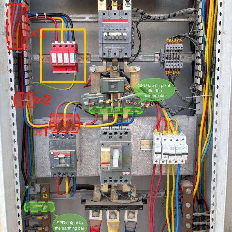
When an MOV or a spark gap conducts a large surge, it momentarily creates a low-impedance path — and the AC source tries to keep feeding current through it after the transient has passed. This power-frequency follow current is an inherent property of every AC arrester. If the SPD cannot clear it, the device keeps dissipating energy until it fails, or the upstream breaker trips and the board loses supply during the next storm.
Follow current behaves differently depending on the technology. MOV-based Type 2 devices limit follow current naturally, because the varistor recovers as the voltage falls back below Uc. Spark-gap and gas-discharge based Type 1 devices rely on the AC zero crossing to extinguish the arc — precisely where AC systems hold an advantage over DC, since a 50/60 Hz arc is interrupted at a current zero every 10 to 20 milliseconds. The failure mode appears where real conditions defeat that advantage: a TT system with high earth-loop impedance can leave too little current to clear the gap cleanly, while a stiff TN supply can deliver so much follow current that the SPD disconnector and the upstream protective device race each other. The classic field symptom is an SPD that operates correctly during the storm, followed by an unexplained breaker trip — a scenario we break down in detail in 5 ways a 50kA surge protector fails and how to prevent it.
Solution: specify devices whose declared follow-current interrupting capability and disconnector behaviour are tested for your earthing system, and never fit a larger upstream fuse “to stop the nuisance trips” — that removes the safety net instead of fixing the coordination. If trips recur, the correct fix is a coordinated backup protector, covered under Cause 5.
Uc — the maximum continuous operating voltage — is the single most consequential number on an AC SPD datasheet, and it is also the most commonly value-engineered. A Uc 275 V device is correct for a well-regulated 230/400 V TN-S supply. Fit that same device on a rural feeder that sits at 250 V all evening, or downstream of a transformer tap set for a long cable run, and the varistor operates permanently near its conduction knee. Leakage current rises, the module runs warm, and end-of-life arrives years early — usually on the hottest day of the year.
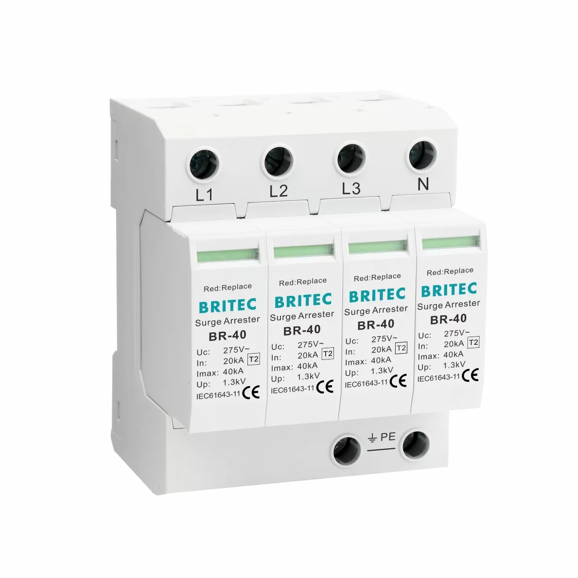
The same logic scales upward. Unstable grids, generator-backed sites, and mining or marine installations with wide voltage excursions justify Uc 320 V or 385 V variants even on 230/400 V nominal systems. And for 690 V industrial networks — large VFD-driven motor loads, hoists, dredgers, test benches — a standard 400 V-class SPD is simply the wrong part; the correct specification is a dedicated high-voltage unit such as the BR-40 4P Type 2 40kA 690 V AC surge protector.
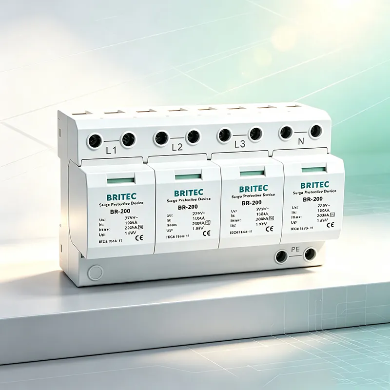
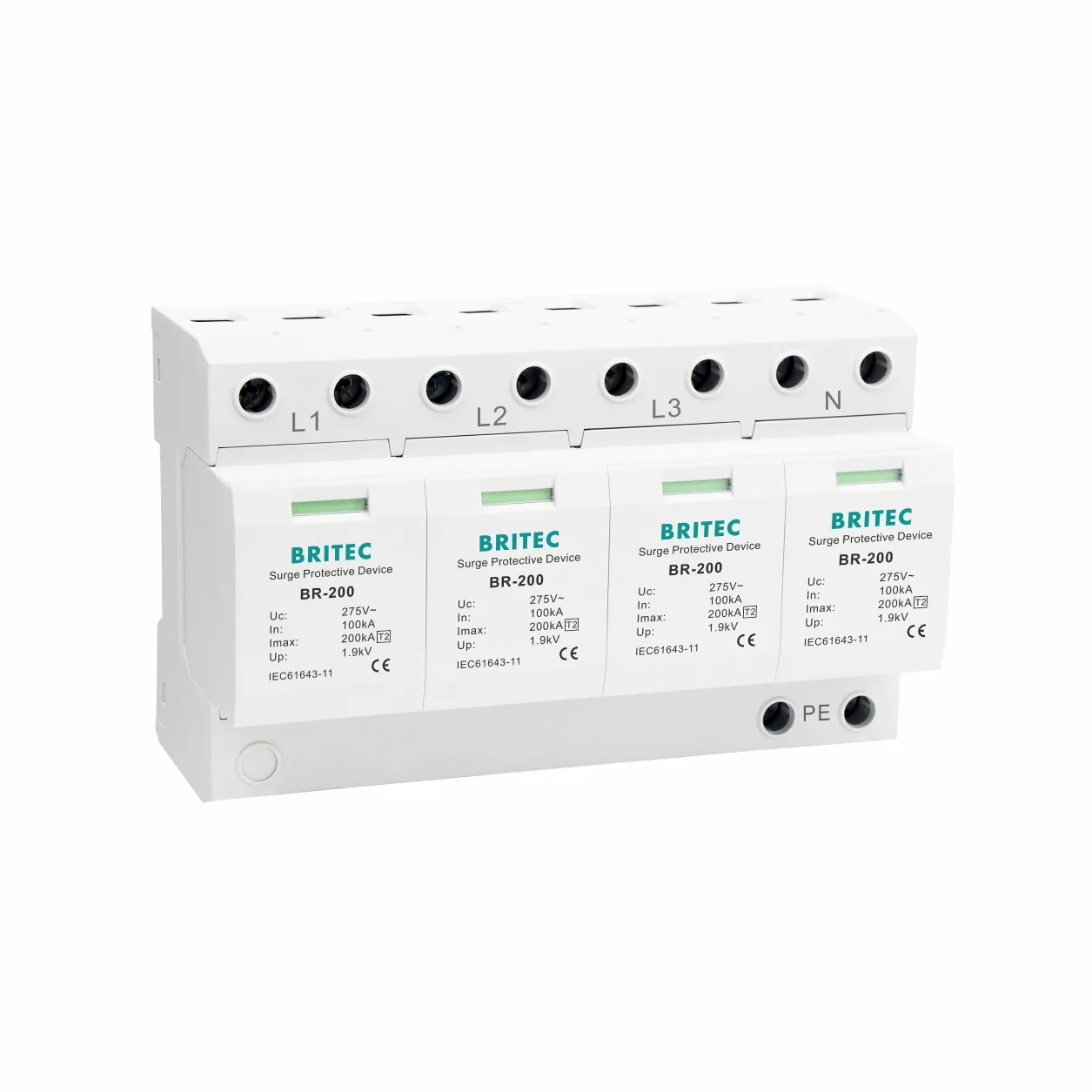
For main distribution boards on stable 230/400 V supplies, the specification logic looks like this: declare Uc 275 V, size In and Imax to the exposure level, and require pluggable modules with a visible status window so that end-of-life is observable instead of silent. The BR-200 series below is one example of that pattern, type-tested to IEC 61643-11 with In 100 kA and Imax 200 kA.
Three checkpoints keep Uc selection honest:
● Measure before you specify — log actual phase-to-neutral voltage for at least a week, including the night-time minimum-load window.
● Match Uc to the measured reality, not the nominal label — step up to a 320 V variant whenever sustained swells or long feeders are documented.
● Confirm Uc per protection mode — in 3+1 configurations the N-PE stage is deliberately sized differently from the L-N stages.
Modern AC loads distort the very waveform the SPD lives in. Third-harmonic currents from single-phase electronics — LED drivers, IT power supplies, variable-speed drives — add in the neutral instead of cancelling, so the neutral conductor and any N-PE connected components carry heating current continuously. An MOV between N and PE in a harmonic-rich panel dissipates that energy around the clock, and its ageing curve accelerates even though not a single surge has occurred.
Power-factor-correction capacitor banks are the second AC-specific stressor. When a bank switches in, the network sees an oscillatory transient that can approach twice the peak voltage, ringing at a frequency set by the upstream inductance and the bank capacitance. Utility and industrial installations that auto-switch capacitor banks on load therefore subject their SPDs to hundreds of clamping events per week that never appear in any lightning statistic. Distributed PV inverters and large VFD front ends add fast, repetitive switching transients of their own.
Solution: where power quality logging shows total harmonic distortion above roughly 8%, or where capacitor banks switch frequently, treat harmonic heating as a design input. Specify SPDs with adequate continuous-duty thermal margins, ensure real ventilation inside the panel, and place filtering or detuning reactors upstream of the correction stages. A thermal-imaging scan of the SPD terminals during peak load is the fastest field check — a healthy module should never run noticeably warm at steady state.
Every AC SPD must be backed by an upstream protective device — fuses or a miniature circuit breaker — so that a shorted SPD can be disconnected without taking the whole board offline. The mismatch problem is that this backup device has two conflicting jobs: it must let the SPD do its surge work, and it must clear a faulted SPD. Size it too small and it trips during normal surge operation, silently leaving the load unprotected for months. Size it too large and a failed SPD cannot be isolated at all.
This is one of the most common root causes we identify in failure investigations from panel-builder and OEM customers, and it is entirely a coordination problem: the declared short-circuit coordination between the SPD and its backup device must be respected, including the maximum permitted backup fuse rating and the breaker curve. Our guide to AC SPD coordination with circuit breakers covers single-phase sizing in detail. The solution is procedural rather than technical: copy the manufacturer’s declared backup values into the single-line diagram, verify the installed device matches, and use remote signalling so that a tripped or disconnected SPD raises an alarm instead of failing quietly.
In a TN-S system the neutral is bonded to earth at the transformer, so a varistor connected between N and PE sees only a few volts in normal service. In a TT system, however, the supply and consumer earth electrodes are separate: the neutral can sit tens of volts above protective earth in normal operation, and an earth fault can hold it there for the full duration of the fault. A 4P SPD with a varistor in the N-PE position is therefore continuously stressed at exactly the point where the 4P design is weakest.
The proven answer in TT installations is the 3+1 configuration: three MOV-equipped phases connected to a common point, and a robust spark gap between N and PE. The spark gap ignores continuous neutral-to-earth voltage, withstands the TOV events that would cook a varistor, and still presents a low-impedance path the moment a real surge arrives. Fitting a 4P all-MOV device into a TT board — or wiring a 3+1 device as if it were 4P — produces a distinctive and easy-to-recognise failure: the N-PE stage fails first while all the phase modules test healthy.
Three wiring rules eliminate this entire failure class:
● Identify the earthing system before choosing the pole format — TN-C, TN-S, and TT each demand different N-PE handling.
● Use a 3+1 format (or 1+1 in single phase) with an N-PE spark gap in TT systems, and reserve all-MOV 4P devices for TN-S.
● Keep connection leads short and straight — every extra centimetre of lead adds inductive voltage in series with the clamp and raises the voltage seen by the load.
Not Sure Which AC SPD Your System Actually Needs?
Britec’s application engineers help B2B buyers match Uc, discharge capacity, and pole configuration to the real supply conditions — TN-S, TT, 690 V, or generator-backed networks. Send us your single-line diagram and receive a specification proposal.
The table below compresses the six causes above into a field diagnostic flow that our engineers use when reviewing customer failure reports. Work from left to right: match the symptom, confirm it with the test, then apply the corrective solution.
| Field Symptom | Likely AC-Specific Root Cause | Confirming Test | Corrective Solution |
|---|---|---|---|
| Status window red on one phase, board otherwise healthy | Sustained TOV from voltage asymmetry or neutral loss (Cause 1) | Log phase-to-neutral voltages for one full week | Inspect and re-torque neutral and PEN links; re-check Uc selection |
| Repeated failures on the same phase within months | Uc too low for the actual supply voltage (Cause 3) | Compare logged voltage against the datasheet Uc | Step up to the next Uc class (275 V → 320 V / 385 V) |
| Upstream breaker or fuse operates during storms | Follow current versus backup protector mismatch (Cause 2 / Cause 5) | Check the installed backup rating against the SPD datasheet | Re-coordinate the backup device; never oversize the fuse |
| N-PE stage failed while phase modules test healthy | 4P all-MOV device installed on a TT system (Cause 6) | Verify the earthing system and N-PE wiring format | Replace with a 3+1 device using an N-PE spark gap |
| Modules discoloured and warm at peak load | Harmonic heating plus poor ventilation (Cause 4) | Thermal scan; power quality logger | Improve airflow, derate, filter or detune the harmonic sources |
| Load running normally but the SPD indicator is dark | SPD disconnected itself after a major surge — silent loss of protection (Cause 5) | Test the remote-signal contacts and status window | Add remote signalling to the BMS and schedule module replacement |
Need This Diagnosis As A Site Survey?
Britec supports panel builders, OEMs, and EPC contractors with failure analysis and specification reviews for AC distribution systems worldwide. Send photos of the failed SPD and the panel schedule — our engineers respond with a diagnosis and a replacement recommendation.
Preventing AC-specific SPD failure is mostly specification discipline plus two habits: measure the supply, and watch the indicators. The sequence below covers the checkpoints that matter most in B2B installations.
● Characterise the supply first — one week of voltage logging reveals swells, asymmetry, and harmonic behaviour that no datasheet assumption can replace.
● Select Uc for the measured reality — 275 V for regulated 230/400 V TN-S supplies; 320 V or 385 V wherever swells or unstable grids are documented.
● Match the pole format to the earthing system — 3+1 with an N-PE spark gap for TT, all-MOV 4P for TN-S.
● Coordinate the backup protector to the SPD datasheet — declared fuse rating and breaker curve, written into the panel design and verified at commissioning.
● Plan for end-of-life — pluggable modules with a visible status window and remote signalling turn a hidden failure into a scheduled maintenance task.
● Inspect on a fixed cycle — status windows after every major storm, a thermal scan annually, and a full electrical test following our guide on how to test an industrial surge protection device.
● Keep records — date-stamped photos of status windows and logged voltage trends make warranty and insurance claims defensible.
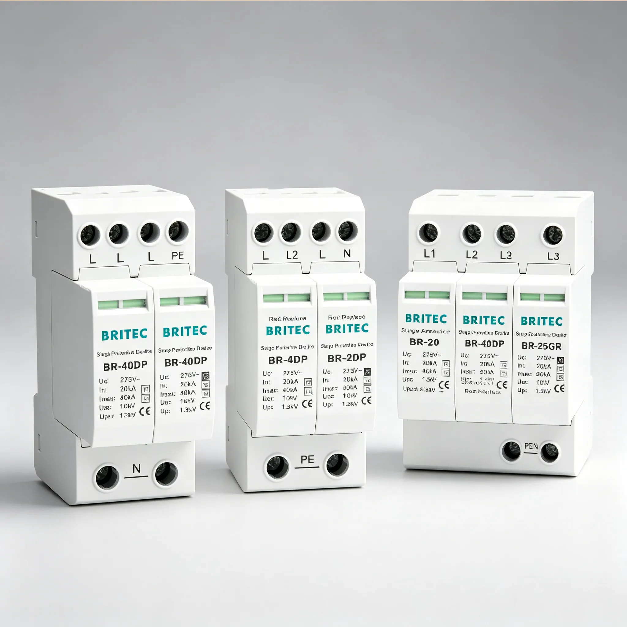
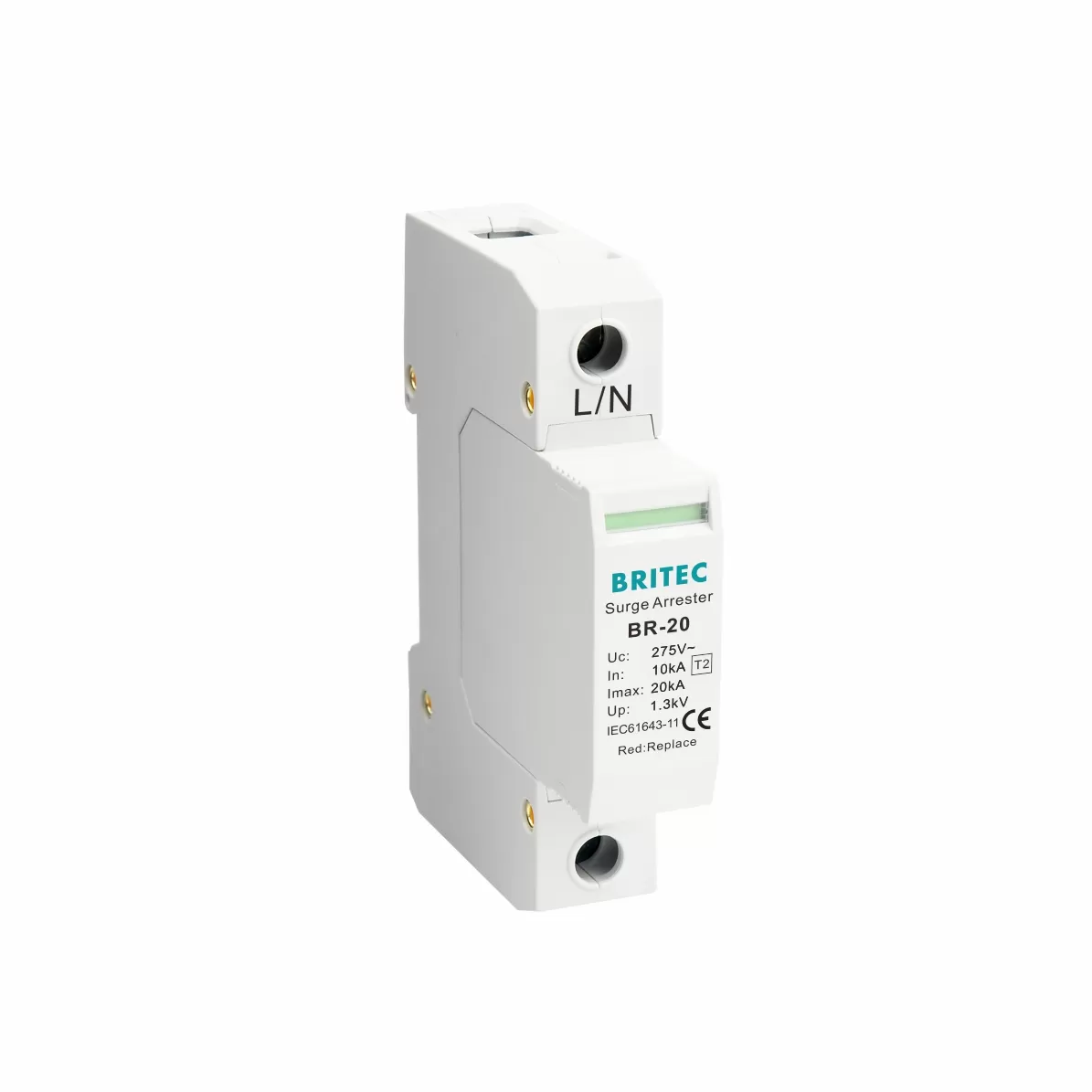
For a reference point on how simple the daily check should be: the status window on a pluggable module such as the BR-20 1P Type 2 20kA surge protective device turns from green to red when the varistor reaches end-of-life — the single most useful field indicator on any AC SPD, and the reason every module in a distributed installation should be visible at eye level.
What AC-side condition destroys a surge protective device fastest?
Sustained temporary overvoltage — typically a lost neutral in a three-phase system or a broken PEN conductor — holds 300–400 V across an MOV rated for 275 V at power frequency. Unlike a surge, the stress does not pass in microseconds, so the varistor heats within seconds. Thermal damage from TOV is the most common catastrophic AC failure we see in returned modules.
Can I use a Uc 275 V SPD on a supply that measures 250 V?
Not indefinitely. A 275 V device carries a margin above the 230 V +10% standard, but a supply that continuously sits at 250 V pushes the varistor close to its conduction knee around every voltage peak. Leakage current and internal heating rise, and end-of-life arrives early. If your logging shows sustained voltages above roughly 245 V, specify a Uc 320 V variant instead.
Why does my SPD blow its upstream fuse every time it operates?
That is a backup-coordination problem, not a defective SPD. The fuse or breaker must match the SPD’s declared backup values: too small and it clears during normal surge duty; too large and a faulted SPD cannot be isolated. Compare the installed device against the datasheet and correct the coordination rather than upsizing the fuse.
What is the difference between a 4P and a 3+1 AC SPD?
A 4P device uses varistors in all four positions, including N-PE. A 3+1 device uses three varistors connected to a common point plus a spark gap between N and PE. On TN-S supplies either arrangement works; on TT systems the 3+1 spark gap is strongly preferred because it tolerates the continuous neutral-to-earth voltage and the TOV events that would destroy an N-PE varistor.
Do harmonics really damage surge protectors?
Yes, indirectly. Third-harmonic currents accumulate in the neutral conductor, so any N-PE connected varistor dissipates heat continuously in harmonic-rich panels. The MOV ages thermally even without a single surge event. Panels supplying large numbers of single-phase electronic loads should be checked with a power quality logger and thermally scanned at peak load.
Why do AC SPDs handle follow current better than DC SPDs?
An AC current passes through zero 100 or 120 times per second, and an arc extinguishes naturally at a current zero. A DC arrester never gets that relief, which is why DC SPDs require specially engineered arc-quenching chambers. The same physics is why an AC-rated SPD must never be deployed on a DC system — the follow current would never clear.
How often should AC SPDs be inspected in a commercial facility?
Check status windows after every significant storm and at every scheduled panel service, perform a thermal scan annually, and run a full electrical test every one to two years — or immediately after any known severe event. Facilities with remote signalling can automate the first check entirely through the BMS.
Which SPD should I specify for a 690 V industrial distribution system?
A 400 V-class SPD is unsafe on 690 V networks. Specify a dedicated high-voltage Type 2 device tested for 690 V AC service — such as a BR-40 690 V variant — and confirm that Uc and Up are declared per IEC 61643-11 for that voltage class. Send us the single-line diagram and our engineers will confirm the correct configuration.
Specify AC Surge Protection Once, Correctly
From 20 kA final-distribution modules to 200 kA main-board arresters, every Britec AC SPD is type-tested to IEC 61643-11 and backed by engineering support in English for international B2B projects.
● Common SPD Surge Protective Device Failure Causes And Solutions
● SPD Neutral Line Fault Analyze
● AC SPD Single Phase Coordination with Circuit Breakers
● How To Test An Industrial Surge Protection Device
● 5 Ways a 50kA Surge Protector Fails and How to Prevent It
● Surge Protection Single Phase vs Three Phase: 5 Differences