
Proper coordination between an AC surge protective device (SPD) and its upstream circuit breaker is one of the most critical and frequently misunderstood aspects of single-phase electrical protection. According to IEC 61643-11, every SPD must be installed with a suitable short-circuit protective device (SCPD) upstream. Without correct coordination, an SPD may nuisance-trip the breaker during normal surge events, fail to disconnect safely at end-of-life, or create a fire hazard during a short-circuit fault. Understanding the principles of AC SPD single phase coordination with circuit breakers is essential for electrical engineers, panel builders, and facility managers responsible for safe and compliant installations.
klo Britec Electric, we have manufactured IEC 61643-11 certified surge protective devices and dedicated backup protectors since 2003. In this technical guide, we cover SCPD selection, MCB tripping curve requirements, single-phase SPD configurations, lead length rules, cascade coordination, and common mistakes to avoid when coordinating AC SPDs with circuit breakers.
Our engineering team helps B2B clients select, configure, and deploy IEC 61643-11 certified surge protection with matched SCPD backup protection for single-phase and three-phase installations. Tell us your system parameters and we will recommend the optimal SPD and circuit breaker coordination.
Surge protective devices and circuit breakers protect against fundamentally different threats. An SPD clamps transient overvoltage (surges lasting microseconds) by diverting surge current to earth. A circuit breaker interrupts sustained overcurrent (overloads and short circuits lasting milliseconds to seconds). Neither device can perform the other’s function. An SPD cannot break a circuit, and a circuit breaker cannot suppress voltage spikes. Both must be present and properly coordinated in any protected installation.
The coordination challenge arises because the SPD and its backup circuit breaker share the same electrical branch. When a surge event occurs, the SPD conducts a high-amplitude, microsecond-duration current pulse. If the backup breaker is too sensitive, it trips during the surge event, disconnecting the SPD and leaving downstream equipment unprotected. If the backup breaker is too insensitive, it fails to disconnect the SPD when the MOV fails short-circuit at end-of-life, creating a sustained fault and fire risk. Proper coordination ensures the breaker allows surge currents to pass through to the SPD while still disconnecting the SPD under fault conditions.
The SCPD (Short-Circuit Protective Device) is the overcurrent protection device installed upstream of the SPD. IEC 61643-11 Clause 8.3.2 mandates that every SPD must have an external SCPD to ensure safe disconnection under fault conditions. The SCPD can be an MCB (Miniature Circuit Breaker), an MCCB (Moulded Case Circuit Breaker), or a fuse.
The core component of most AC SPDs is the metal oxide varistor (MOV). MOVs degrade with each surge event, absorbing energy and gradually losing clamping capability. After repeated surges or a severe over-stress event, an MOV can fail in short-circuit mode, creating a direct connection between the line conductor and earth. On a low-impedance busbar, this fault current can reach tens of kiloamperes. Without a functional SCPD upstream, this fault current flows continuously, overheating the SPD enclosure until it melts or catches fire.
Many SPDs include an internal thermal disconnection device that physically separates the MOV from the circuit when it reaches a critical temperature. This thermal disconnect is the first line of defense against MOV failure. However, the thermal disconnect alone cannot interrupt high short-circuit currents. If the prospective short-circuit current at the installation point exceeds the thermal disconnect’s breaking capacity, the SCPD must clear the fault. This is why IEC 61643-11 requires both the internal thermal disconnect and the external SCPD to work together as a coordinated protection system.
The SCPD serves two distinct functions in SPD coordination:
Single-phase installations use several SPD pole configurations depending on the earthing system (TN-S, TN-C-S, TT, or IT). Understanding which configuration applies to your installation is the first step in proper SCPD coordination.
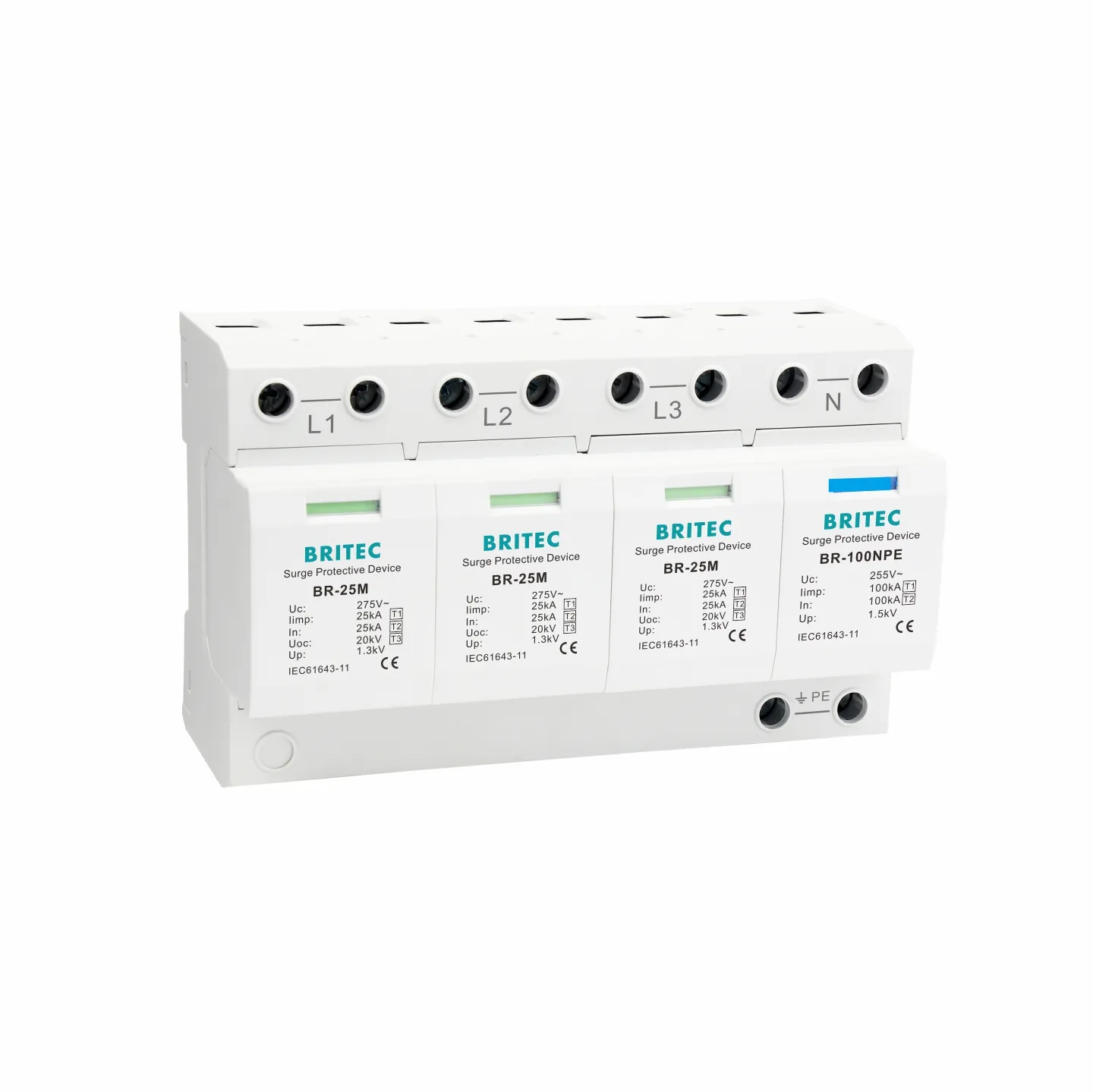
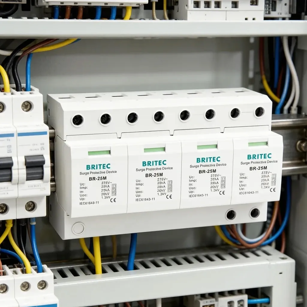
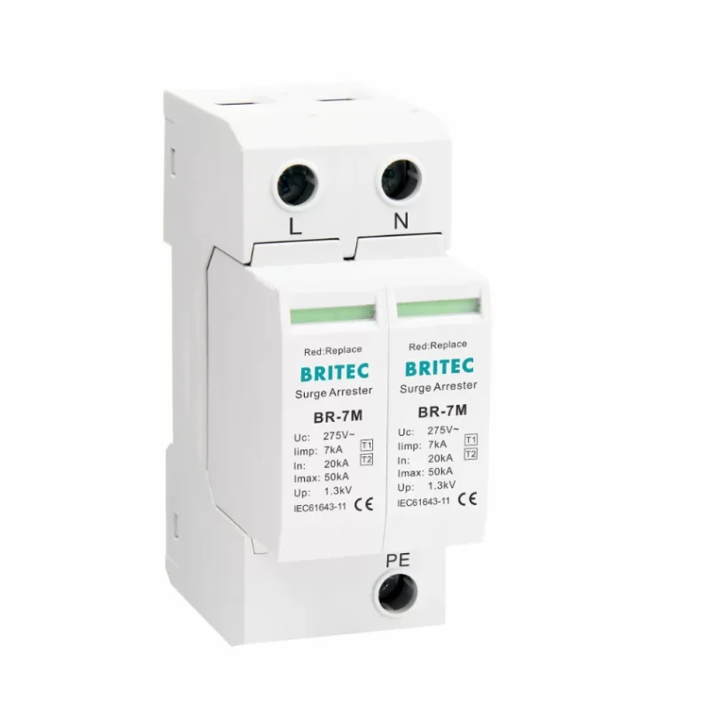
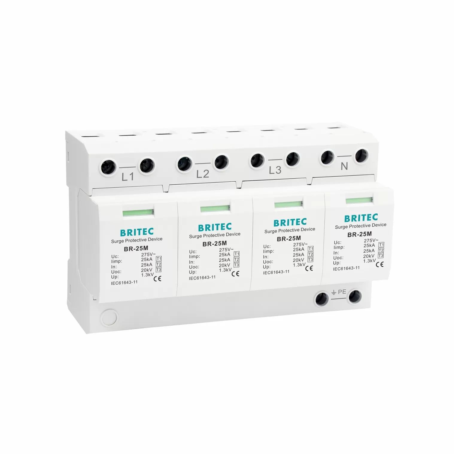
A 1P SPD protects between the line conductor and protective earth (L-PE). This configuration is used in TN-S and TN-C-S systems where the neutral and protective earth conductors are separate from the service entrance. The SPD clamps overvoltage between phase and earth. For example, the BR-25M 1P Tyypin 1 25 kA ylijännitesuoja provides L-PE protection with Iimp of 25kA and a maximum backup fuse of 200A gG.
A 1+1 SPD configuration consists of two modules: one protecting between line and neutral (L-N) and one protecting between neutral and protective earth (N-PE). This configuration is required for TT earthing systems and TN-S systems where the neutral-earth bond is at the transformer. The 1+1 configuration eliminates continuous leakage current on the PE conductor, making it compatible with RCDs. The BR-25M 1+1 Type 1 25kA Surge Arrester for TT and TN-S provides Iimp of 25kA per pole (50kA total) with a maximum backup fuse of 200A gG.
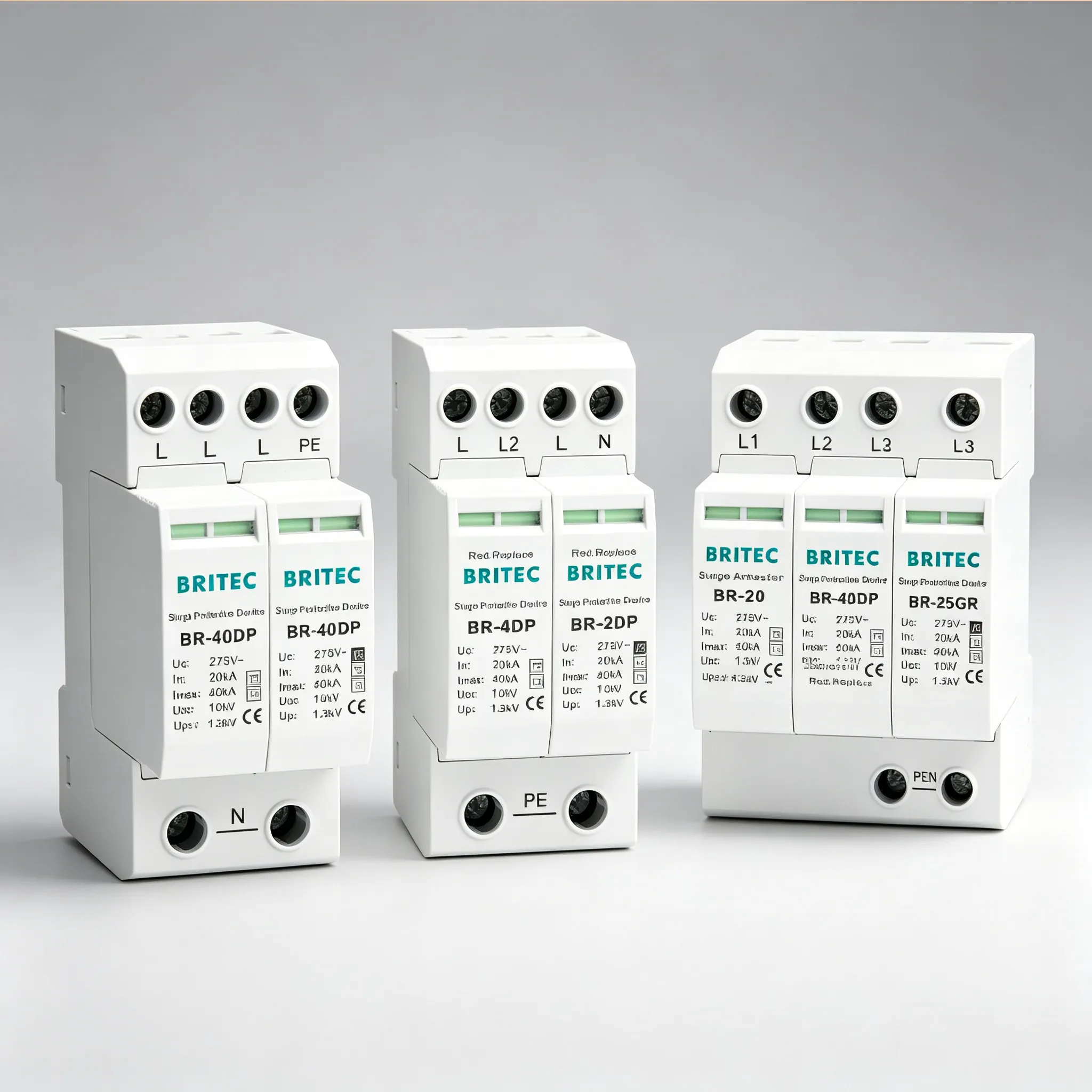
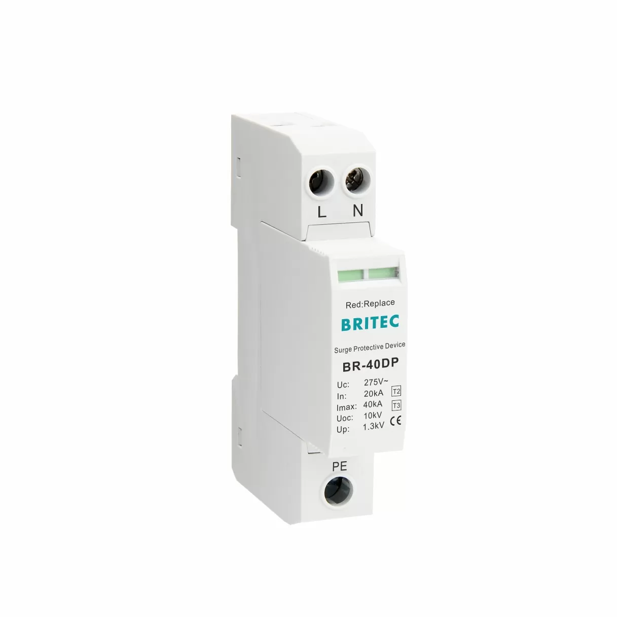
A 2P SPD protects between line and neutral (L-N) and is used in TN-S systems where the N-PE bond is at the installation. Both poles protect the L-N circuit, providing balanced clamping. The BR-40DP 2P 40kA Compact SPD offers Imax of 40kA with a compact DIN-rail footprint, suitable for sub-distribution boards in single-phase TN-S installations.
Selecting the correct SCPD depends on the SPD type (Type 1, Type 2, or Type 1+2), its discharge current rating (Iimp or Imax), and the prospective short-circuit current at the installation point. The following table provides general guidance based on IEC 61643-11 coordination principles:
| SPD Type | Discharge Current | Recommended SCPD | MCB Curve |
|---|---|---|---|
| Tyyppi 1 | Iimp 25kA | 100A to 200A gG fuse | D curve |
| Tyyppi 1+2 | Iimp 12.5kA | 80A gG fuse or 63A MCB | C or D curve |
| Tyyppi 2 | Imax 40kA | 32A to 63A MCB or dedicated SCB | C curve |
| Tyyppi 2 | Imax 20kA | 16A to 25A MCB | C curve |
| Tyyppi 3 | Imax 20kA | 16A or 20A MCB | C curve |
Always verify the maximum SCPD rating printed on the SPD datasheet or product label. Never exceed the manufacturer’s specified maximum. For installations with prospective short-circuit currents exceeding 25kA, dedicated SPD backup protectors or gG fuses with adequate breaking capacity are required.
The tripping characteristic curve of the MCB used as the SCPD is just as important as its current rating. The curve determines how the breaker responds to different overcurrent levels. Using the wrong curve is one of the most common causes of SPD coordination failure.
Type B MCBs trip when the current reaches 3 to 5 times the rated current. These breakers are highly sensitive to sudden inrush currents and are designed for applications with long cable runs and low inrush. When used as an SPD backup, a Type B MCB will likely nuisance-trip during the brief inrush pulse when the SPD first activates during a surge event. The breaker disconnects the SPD precisely when it is most needed, leaving downstream equipment unprotected. Never use a Type B MCB as the SCPD for an SPD.
Type C MCBs trip at 5 to 10 times rated current. This higher magnetic trip threshold sits above typical SPD discharge current peaks, allowing the microsecond-duration surge to pass through to the SPD without tripping the breaker. At the same time, the thermal trip element still disconnects the SPD when a sustained 50/60Hz short-circuit fault occurs (such as when the MOV fails). Type C is the preferred curve for most commercial and light industrial single-phase SPD installations.
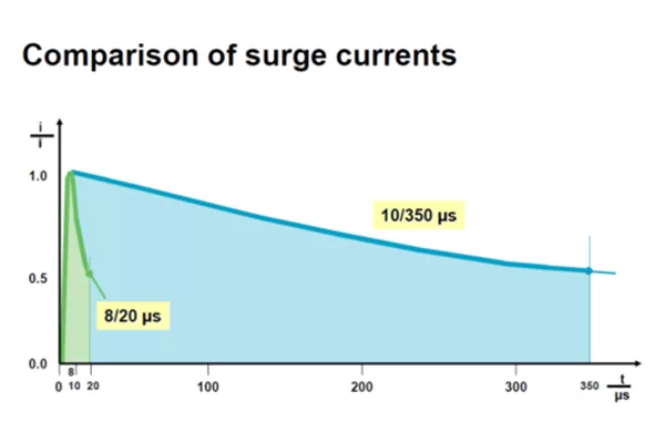
Type D MCBs trip at 10 to 20 times rated current. These breakers tolerate very high inrush currents and are used in industrial environments with large motor starting currents, transformers, or high-exposure lightning zones. Type D curve is recommended for Type 1 SPDs at service entrances where the prospective short-circuit current is high and the SPD must handle partial lightning current (10/350µs waveform).
Even with the correct SCPD and MCB curve, poor wiring can undermine SPD coordination. IEC 61643-12 specifies that the total lead length from the busbar to the SPD to the PE bar should not exceed 0.5 metres. This is because every metre of conductor adds approximately 1 microhenry of inductance, and the voltage drop across this inductance during a surge event is additive to the SPD’s voltage protection level (Up).
The effective residual voltage at the protected equipment is calculated as:
Uresidual = Up + (L × di/dt)
Where Up is the SPD’s voltage protection level, L is the total lead inductance, and di/dt is the rate of change of the surge current. For an 8/20µs waveform with 20kA peak current, di/dt can reach 2kA/µs. With just 0.5 metres of lead (approximately 0.5µH), the additional voltage drop can exceed 1000V, effectively doubling the Up seen by the equipment.
To minimize lead length impact:
In single-phase systems with multiple SPD types (for example, a Type 1 at the service entrance and a Type 2 at the sub-distribution board), the coordination between the two SPDs is governed by the 10-metre cascade rule. This principle, derived from IEC 61643-12, requires a minimum of 10 metres of cable between a Type 1 and a Type 2 SPD installation point.
The reason is that the Type 2 SPD, with its faster response time, will conduct before the Type 1 if they are too close together. This causes the Type 2 to absorb more energy than it is rated for, leading to premature failure and leaving the system unprotected. The 10 metres of cable provides approximately 10µH of natural inductance, which ensures the Type 1 SPD conducts first during a high-energy event, directing the bulk of the surge energy to earth through the higher-rated device.
If the physical distance between the main switchboard and the sub-distribution board is less than 10 metres, two solutions are available:
While standard Type C or D curve MCBs can serve as the SCPD, they are not optimized for the unique current-time characteristics of surge events. Standard MCBs are designed for 50/60Hz overcurrent protection and may allow excessive follow current or leakage current to persist after the SPD activates. Dedicated SPD backup protectors (SCBs) are specifically engineered to address these limitations.
The BRSCB-40 Class II Dedicated Backup Protector is designed for Type 2 SPDs with Imax up to 40kA. Available in 1P, 2P, 3P, and 4P configurations, it can cut leakage current to under 3A, withstand high impulse currents without nuisance tripping, and coordinate precisely with SPD end-of-life behavior. For Type 1 SPDs, the BRSCB-I-25 Class I Dedicated Backup Protector handles lightning impulse currents up to 25kA (10/350µs) and Imax of 100kA (8/20µs).
For installers who prefer an all-in-one solution, the BRCB-15/30/40 Type 2 SPD Combined with MCB integrates the surge protective device and miniature circuit breaker into a single DIN-rail module. The manufacturer has already tested the SPD and MCB as a matched pair, eliminating the need for separate SCPD selection and coordination engineering. The BRCB-40 model offers Imax of 40kA with a 32A MCB, while the BRCB-15 offers Imax of 15kA with a 16A MCB.
Even experienced engineers make coordination errors. Here are the most common mistakes and how to avoid them:
Whether you need a single-phase Type 2 SPD with matched MCB or a complete cascading protection system with dedicated backup protectors, our team provides professional specification support and fast quotes within 24 hours.
An AC SPD contains metal oxide varistor (MOV) components that can fail in short-circuit mode after repeated surge events or severe over-stress. When an MOV fails short, it connects the line directly to earth, creating a fault current path that can reach tens of kiloamperes on a stiff busbar. Without a backup short-circuit protective device (SCPD) upstream, this fault current continues indefinitely, overheating the SPD and creating a fire hazard. IEC 61643-11 Clause 8.3.2 mandates that every SPD must have an external SCPD installed upstream to safely disconnect the SPD under fault conditions.
Always use Type C or Type D curve MCBs as the backup protection device for SPDs. Type B MCBs trip at 3 to 5 times rated current and may nuisance-trip during the brief inrush pulse when the SPD first activates during a surge event, disconnecting the SPD precisely when it is most needed. Type C MCBs trip at 5 to 10 times rated current, and Type D MCBs trip at 10 to 20 times rated current. Both C and D curves tolerate the microsecond-duration surge current without tripping, while still providing reliable short-circuit disconnection when the SPD reaches end-of-life.
For single-phase Type 1 SPDs with Iimp of 25kA, such as the Britec BR-25M 1P series, the maximum permitted backup fuse is 200A gG. For Type 1+2 combined SPDs with lower Iimp (12.5kA), a 125A gG fuse or 80A MCB is typical. Always verify the maximum SCPD rating printed on the SPD datasheet or product label. Never exceed the manufacturer’s specified maximum backup protection rating, and never install an SCPD rated lower than the SPD’s minimum requirement.
A standard Type C or D curve MCB can serve as the SCPD for an SPD, but it has limitations. Standard MCBs are not optimized for the unique current-time characteristics of surge events and may allow excessive leakage current to persist before tripping. Dedicated SPD backup protectors, such as the Britec BRSCB-40 for Type 2 and BRSCB-I-25 for Type 1, are specifically engineered to cut leakage current to under 3A, withstand high impulse currents without nuisance tripping, and coordinate precisely with SPD end-of-life behavior. For critical installations, dedicated backup protectors provide superior safety and coordination.
According to IEC 61643-12, the total lead length from the busbar to the SPD to the PE bar should not exceed 0.5 metres. Every extra centimetre of lead adds inductance, which raises the effective voltage protection level (Up) at the protected equipment. Excessive lead length can increase the residual voltage by hundreds of volts, negating the SPD’s clamping performance. The conductor cross-section should be at least 6mm² for Type 1 and Type 2 SPDs, and the earth resistance at the PE bar should be below 10 ohms.
When a Type 1 SPD and a Type 2 SPD are installed in the same system, they must be separated by at least 10 metres of cable between their installation points. If they are too close, the faster-responding Type 2 activates before the Type 1 has time to conduct, causing the Type 2 to absorb more energy than it is rated for and fail prematurely. If the physical distance is less than 10 metres, install a decoupling coordination inductor (10 to 15µH) between the Type 1 and Type 2 positions, or use a combined Type 1+2 device at the main board.
Yes. When an SPD diverts surge current to earth, the resulting line-to-neutral current imbalance can trigger an RCD downstream. To avoid nuisance trips, install the SPD upstream of the RCD on a separate SCPD branch. If the SPD must sit downstream of an RCD, select an RCD with surge immunity (S-type or HI-type) and verify that the SPD’s standing leakage current stays below 30% of the RCD’s rated residual operating current. This is particularly important in single-phase TT systems where 1+1 SPD configurations are used.
A 1P (single-pole) SPD protects between line and protective earth (L-PE) and is used in TN-S and TN-C-S systems. A 1+1 (1P+N) SPD configuration consists of two modules: one between line and neutral (L-N) and one between neutral and protective earth (N-PE). The 1+1 configuration is required for TT earthing systems and TN-S systems where the neutral-earth connection is at the transformer. The 1+1 configuration also eliminates continuous leakage current on the PE conductor, making it compatible with RCDs.
Both fuses and MCBs can serve as the SCPD, but each has trade-offs. gG fuses offer higher breaking capacity and faster short-circuit clearing times, making them preferred for high prospective short-circuit current installations. MCBs offer the convenience of resettable operation and visual trip indication. For single-phase Type 2 SPDs with In up to 20kA, a Type C MCB rated 25A to 63A is commonly used. For Type 1 SPDs with Iimp of 25kA, gG fuses rated 100A to 200A are preferred. Dedicated SPD backup protectors combine the best characteristics of both.
Yes. Combined SPD-MCB products, such as the Britec BRCB-15/30/40 series, integrate a Type 2 surge protective device and a miniature circuit breaker into a single DIN-rail module. This eliminates the need for separate SCPD selection and coordination, as the manufacturer has already tested the SPD and MCB as a matched pair. The BRCB-40 model offers Imax of 40kA with a 32A MCB, while the BRCB-15 offers Imax of 15kA with a 16A MCB. Combined products are ideal for panel builders and installers who want guaranteed coordination without engineering the SCPD sizing themselves.