Power surges are silent killers in modern electrical systems. From residential electronics to industrial automation and solar plants, even a single transient overvoltage can cause downtime, costly repairs, or equipment failure. The solution? Surge Protection Devices (SPDs).
In this guide, we’ll break down the different Types of Surge Protection Devices, explain how they work, and compare their applications. By the end, you’ll know exactly which SPD types fit your system — whether it’s a home, data center, or PV installation.
A Surge Protection Device (SPD) is a safety component installed in an electrical system to limit transient overvoltages caused by lightning strikes, switching events, or utility disturbances. It works by diverting surge energy safely to earth, protecting connected equipment.
Think of an SPD as a pressure-release valve: it doesn’t stop the surge from happening, but it channels the excess energy away from sensitive electronics.
SPDs rely on components such as Metal Oxide Varistors (MOVs), Gas Discharge Tubes (GDTs), and spark gaps. When voltage exceeds a safe threshold (Uc), the SPD switches into conduction mode, clamping the surge to a lower residual voltage (Up).
Key parameters to understand:
Uc (Maximum Continuous Operating Voltage): the normal voltage the SPD can handle.
Up (Voltage Protection Level): clamping voltage that downstream devices will “see.”
In / Imax (Nominal & Maximum Discharge Current): how much surge current the device can absorb.
Iimp (Impulse Current): specific to Type 1, representing lightning strike waveforms.
Understanding SPD types is the key to designing layered surge protection. International standards such as IEC 61643-11 (AC), IEC 61643-31 (DC/PV), and UL 1449 (North America) define different classes based on test waveforms, energy capability, and installation location.
Below, we break down the different types of surge protection devices (SPDs) you’ll encounter, with their technical roles and application guidance.
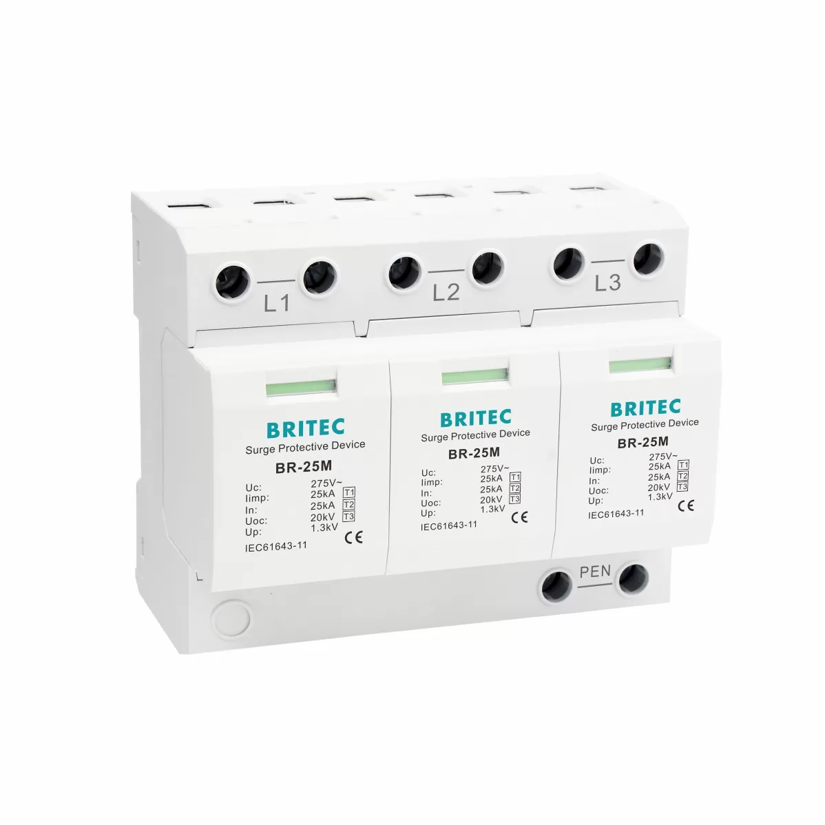
Definition: Designed to discharge partial lightning current. Tested with the 10/350 µs impulse waveform (Iimp) representing a direct lightning strike.
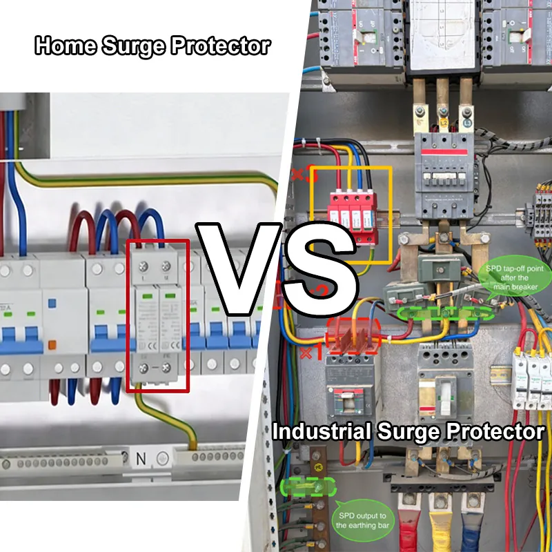
Installation Point: Service entrance, typically upstream of the main distribution board. Often used in buildings equipped with an external Lightning Protection System (LPS).
Key Parameters:
Iimp (Impulse Current): rated lightning current capacity.
Uc (Maximum Continuous Operating Voltage): ensures no damage during normal operation.
Up (Voltage Protection Level): residual voltage seen by downstream circuits.
Technology Used: Spark gaps, heavy-duty MOVs, or hybrid designs.
Use Cases:
Industrial facilities, telecom towers, hospitals.
Tall buildings in high lightning density regions.
Example: A factory with rooftop lightning rods will require Type 1 SPDs at the main incoming supply.
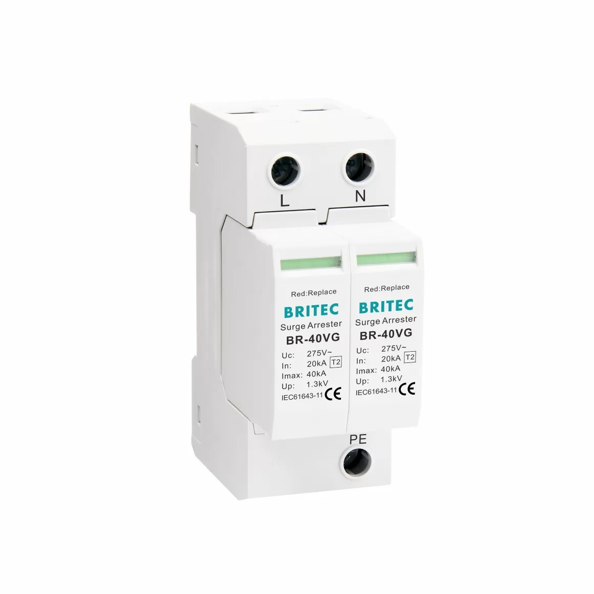
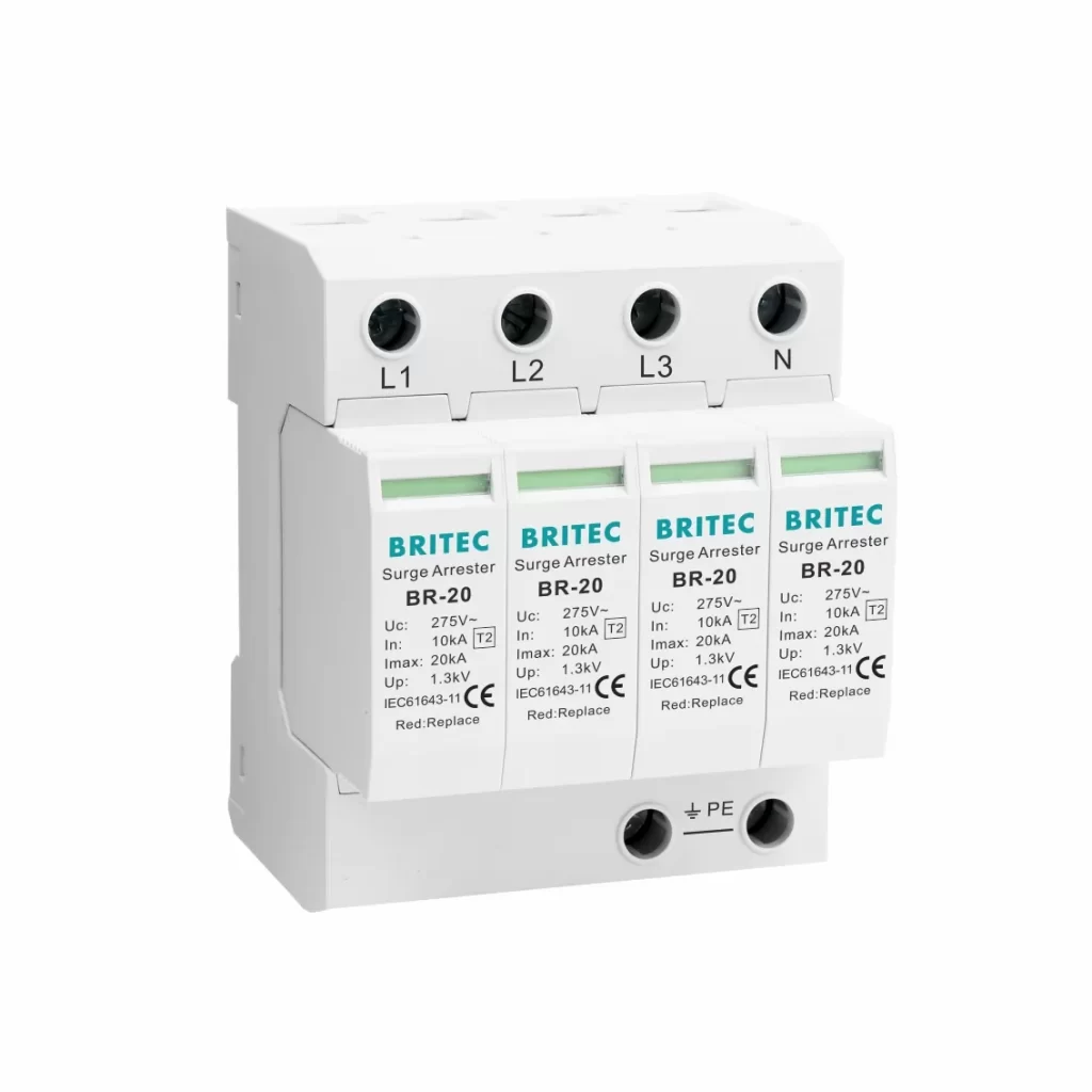
Definition: Handles switching surges and indirect lightning effects. Tested with 8/20 µs current waveform (In, Imax).
Installation Point: Main or sub-distribution boards inside the facility.
Key Parameters:
In (Nominal Discharge Current): endurance under multiple surges.
Imax (Maximum Discharge Current): maximum surge capability.
Up: must coordinate with both upstream Type 1 and downstream Type 3.
Technology Used: MOV-based modules, often pluggable for easy replacement.
Use Cases:
Residential homes, office buildings, retail stores.
Standard protection in areas with moderate surge risk.
Example: A small office without external LPS would typically use Type 2 SPDs in the main board.
Want a detailed breakdown? Read our full guide: What Is a Type 2 Surge Protection Device?
Definition: Fine protection for terminal equipment. Tested with combination wave (1.2/50 µs voltage + 8/20 µs current).
Installation Point: As close as possible to the protected device (socket outlet, device input).
Key Parameters:
Up: very low clamping level to protect sensitive loads.
Must be used in coordination with upstream Type 2.
Technology Used: MOVs combined with filters for extra attenuation.
Use Cases:
Computers, LED drivers, medical electronics, and control systems.
Example: A hospital MRI machine requires Type 3 SPD near the device, working together with upstream Type 2.
Learn more in our dedicated article: What Is a Type 3 Surge Protector?
Definition: A single SPD unit tested for both Class I (10/350 µs) and Class II (8/20 µs) waveforms.
Benefit: Protects against direct lightning as well as switching surges in one device.
Installation Point: Service entrance when space or budget limits multiple devices.
Use Cases:
Medium-sized commercial or residential buildings need compact solutions.
Sites where coordination between separate Type 1 and Type 2 is difficult.
Example: A shopping mall’s main switchboard may install a T1+T2 SPD to simplify protection.
Definition: Hybrid devices are tested for Class II and Class III performance.
Benefit: Provides both distribution-level and terminal protection.
Installation Point: Sub-panels close to sensitive loads, especially if cable runs exceed 10 m.
Use Cases:
Data centers, server rooms, industrial control cabinets.
Example: A factory automation line with long cable runs to PLCs can use a T2+T3 SPD near the PLC panels.
Definition (UL 1449): Component assemblies not intended as stand-alone devices but integrated into OEM equipment.
Subcategories:
Type 4 Component Assemblies (CA): pre-packaged SPD parts for manufacturers.
Type 5 Components: raw MOVs or GDTs.
Installation Point: Inside appliances, power supplies, or custom-built panels.
Use Cases:
OEMs designing surge-protected equipment.
Specialized industrial gear in the North American market.
Example: A UPS manufacturer integrates Type 4 SPD assemblies inside its products.
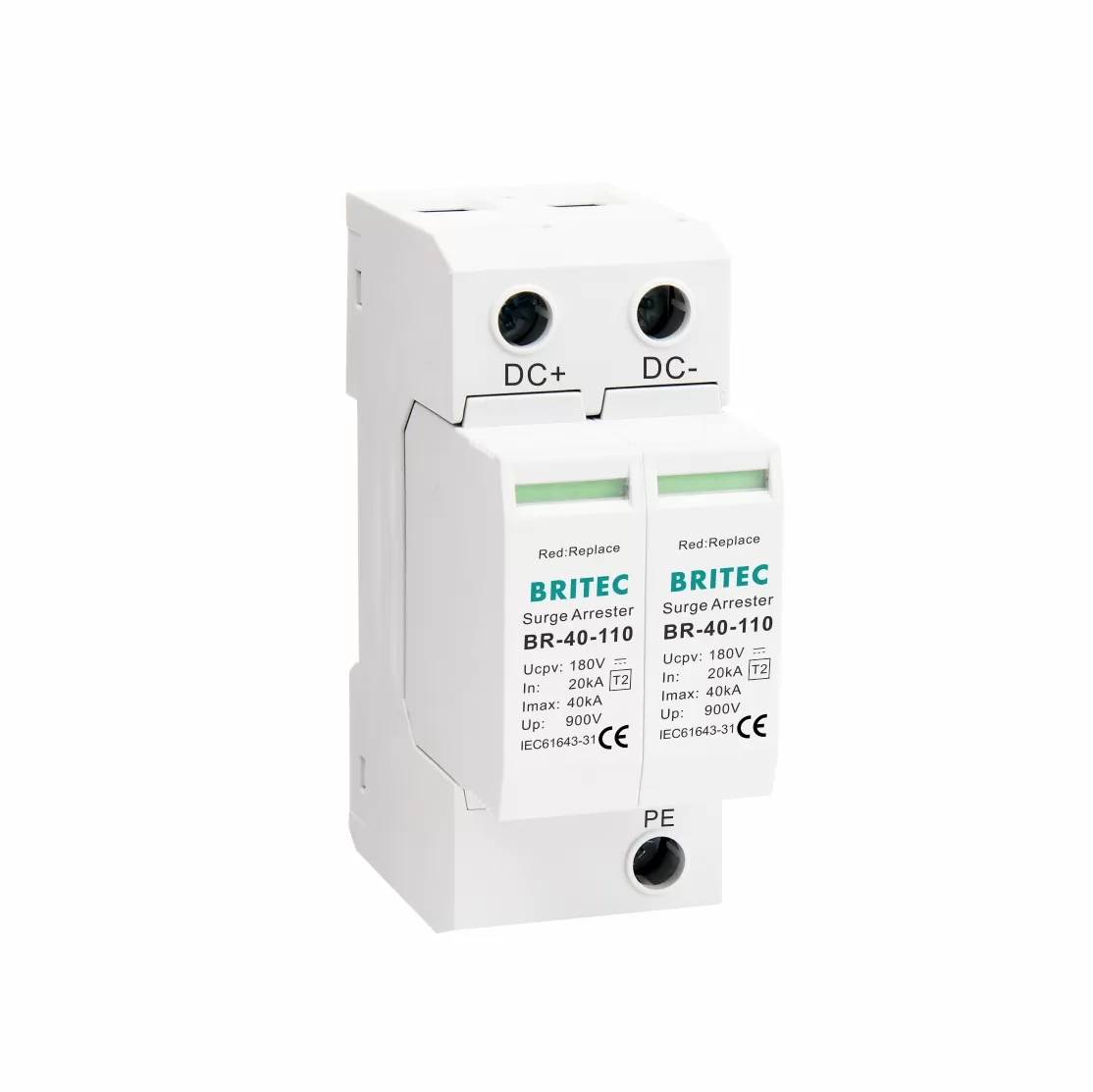
Definition: Surge protection devices designed for photovoltaic and DC circuits.
Test Standards: IEC 61643-31 specifies requirements for DC applications.
Installation Point: PV array combiner boxes, inverters, and DC distribution boards.
Key Parameters:
Ucpv: rated continuous PV voltage (600 V, 1000 V, 1500 V).
In / Imax: surge current handling on the DC side.
Response time: must be fast enough for semiconductor-based inverters.
Use Cases:
Utility-scale solar farms, rooftop PV systems, battery storage facilities.
Example: A 1500 VDC solar farm will need T1+T2 PV SPDs at combiner boxes and inverter inputs.
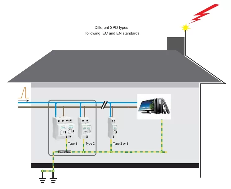
Pro Tip for readers: Always use a coordinated SPD system. Type 1 at the entrance, Type 2 at sub-panels, and Type 3 close to critical loads. For PV, add Type 2 or T1+T2 DC SPDs as specified by IEC 61643-31.
If you want a deeper dive, check our dedicated blog on this topic here:
Difference Between Type 1, Type 2, and Type 3 SPDs
Here’s a quick comparison to help you choose the right SPD type:
| Attribute | Type 1 SPD | Type 2 SPD | Type 3 SPD |
|---|---|---|---|
| Tested Standard | IEC 61643-11 Class I (10/350 µs) + dual-rated UL Type 1/2 | IEC 61643-11 Class II (8/20 µs) + UL Type 2 | IEC 61643-11 Class III (combination wave) + UL Type 3 |
| Typical Location | Service entrance / Main switchboard | Inside distribution boards/sub-panels | Within 1 m of critical loads (computers, drivers, medical gear) |
| Primary Function | Handle direct lightning current; protect building entrance | Handle modular surges from switching, fault arcs, etc. | Suppress residual energy for sensitive electronics. |
| Parameter Focus | High impedance; Uc ≥ system voltage; Up coordination | In Imax, Up cascading with upstream/downstream SPDs | Ultra-low Up; precise clamping to protect sensitive loads |
| Installation Note | Needs large wiring (≥16 mm²); can be installed without upstream OCPD; must be coordinated with Type 2 | Requires upstream overcurrent protection; wiring ≥6 mm² | Very close to load; supplement to upstream Type 2 |
| Use Cases | Buildings with LPS, tall structures, and high lightning zones | Most homes, commercial facilities, and industrial sub-panels | PC clusters, PLC racks, LED/medical systems |
Type 1 SPDs handle high-energy, direct lightning strokes (10/350 µs).
Type 2 SPDs mitigate switching surges and indirect strikes (8/20 µs).
Type 3 SPDs protect sensitive equipment at the last mile (combination waveform).
Correct installation is just as critical as selecting the right Types of Surge Protection Devices (SPD). Improper wiring or poor coordination can compromise protection levels, even if the SPD itself meets IEC or UL standards. Based on IEC 61643-11, IEC 61643-31, UL 1449, and our company’s engineering guidelines, here are the key best practices:
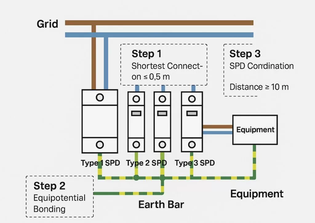
Keep all SPD connecting leads as short and straight as possible, ideally ≤ 0.5 m (as recommended in our technical manual).
Long leads introduce inductive voltage rise, which increases the residual voltage (Up) seen by the protected equipment.
Use conductors sized according to the SPD type:
Type 1 SPD: minimum 16 mm² copper (high-energy lightning current, Iimp).
Type 2 SPD: minimum 6 mm² copper.
Type 3 SPD: follow the manufacturer’s data, typically smaller cross-sections due to lower current.
Always use copper conductors with low impedance and avoid sharp bends.
All SPDs must be connected to the same main earthing bar or equipotential bonding system.
Bonding ensures surge energy is safely discharged to ground, avoiding dangerous potential differences between circuits.
Voltage Protection Level (Up) Hierarchy: Upstream SPDs (Type 1) should always have a higher Up than downstream SPDs (Type 2/3).
Distance Rule: If the cable between SPDs and protected loads is longer than 10 m, install an additional downstream SPD (e.g., Type 3) for better protection.
Parallel Coordination: For multi-stage protection (Type 1 + Type 2 + Type 3), ensure proper energy distribution so that no single device is overstressed.
Always use dedicated fuses or circuit breakers to protect the SPD itself.
Our manual specifies back-up fuse ratings depending on SPD model and Imax/Iimp.
UL 1449 also requires proper overcurrent protection to prevent SPD overheating or failure during extreme events.
Pro Tip: Always verify compliance with IEC 61643-11 (AC SPDs), IEC 61643-31 (PV/DC SPDs), or UL 1449 (North America) depending on your region. Correct installation and coordination maximize SPD lifetime and ensure safety of the entire electrical system.
Types of Surge Protection Devices are not interchangeable — each plays a unique role in defending electrical systems.
Type 1 shields against direct lightning strikes.
Type 2 is the workhorse for distribution boards.
Type 3 protects your most sensitive electronics.
Combinations and PV/DC SPDs cover specialized and renewable applications.
By understanding SPD types, their standards, and installation rules, you can design a layered defense that ensures safety, minimizes downtime, and protects investments.
 Optimized by Seraphinite Accelerator