Power surges are one of the most common causes of electrical equipment failure. While lightning strikes account for some surges, the majority are caused by switching operations, motors, or disturbances within the grid itself. That’s where a Type 2 surge protector comes in.
Type 2 SPDs (Surge Protective Devices) are installed in the main distribution board or upstream of UPS systems. Their job is to clamp down on transient overvoltages and safely divert surge currents to ground, keeping your sensitive devices safe.
In this guide, we’ll break down how to install a Type 2 surge protector step by step. You’ll learn the tools you need, safety checks, wiring diagrams, and testing methods. And we’ll go deeper than most beginner blogs—referencing IEC 61643 standards, wiring best practices, and practical engineering tips that will save you from costly mistakes.
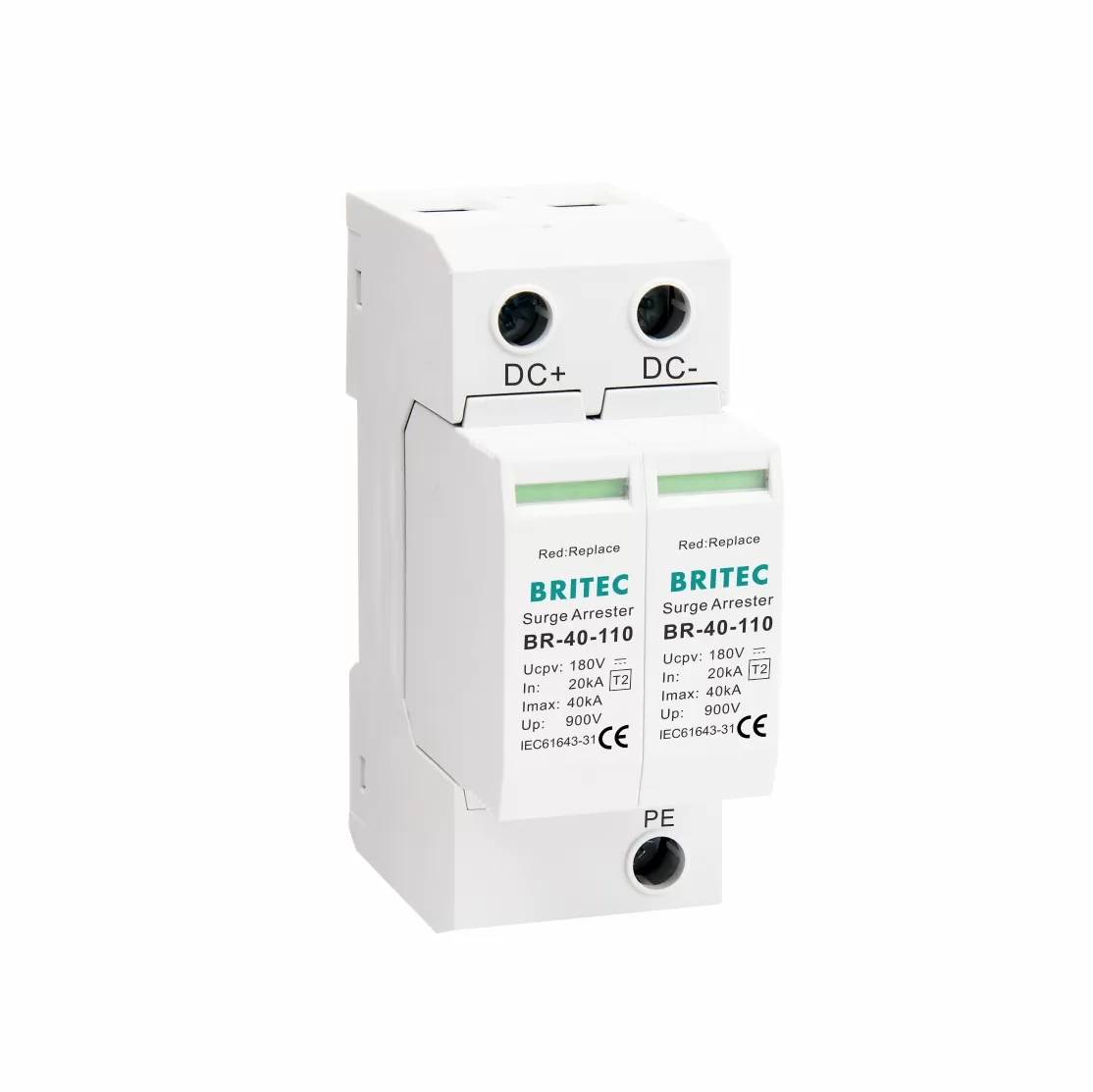
A Type 2 SPD is designed to handle surge currents from indirect lightning strikes and switching operations.
Where it goes: Installed in the main distribution board (consumer unit) or on the input side of UPS systems.
What it protects against: Induced lightning surges, switching transients, grid disturbances.
How it works: By clamping the surge voltage (Up) and diverting energy to the earth (PE).
Key parameters defined by IEC 61643:
Uc (Max Continuous Operating Voltage): The maximum RMS voltage the SPD can handle continuously.
Up (Voltage Protection Level): The clamping level that remains on the protected side.
In (Nominal Discharge Current): Surge current the SPD can withstand repeatedly (8/20 μs waveform).
Imax (Maximum Discharge Current): The largest single surge the SPD can survive.
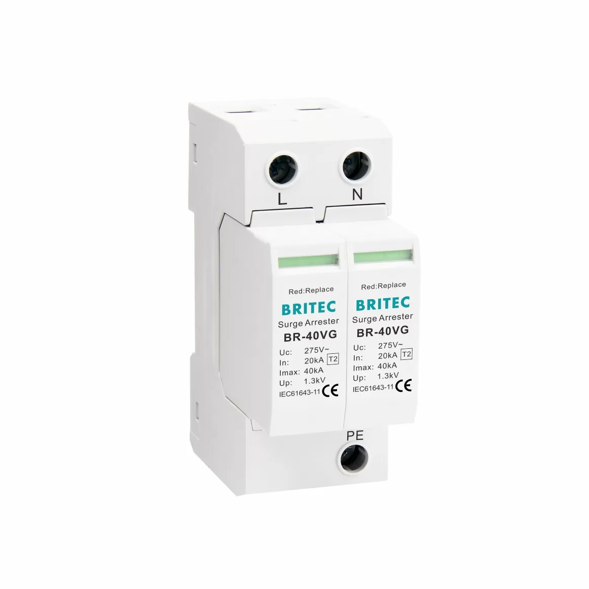
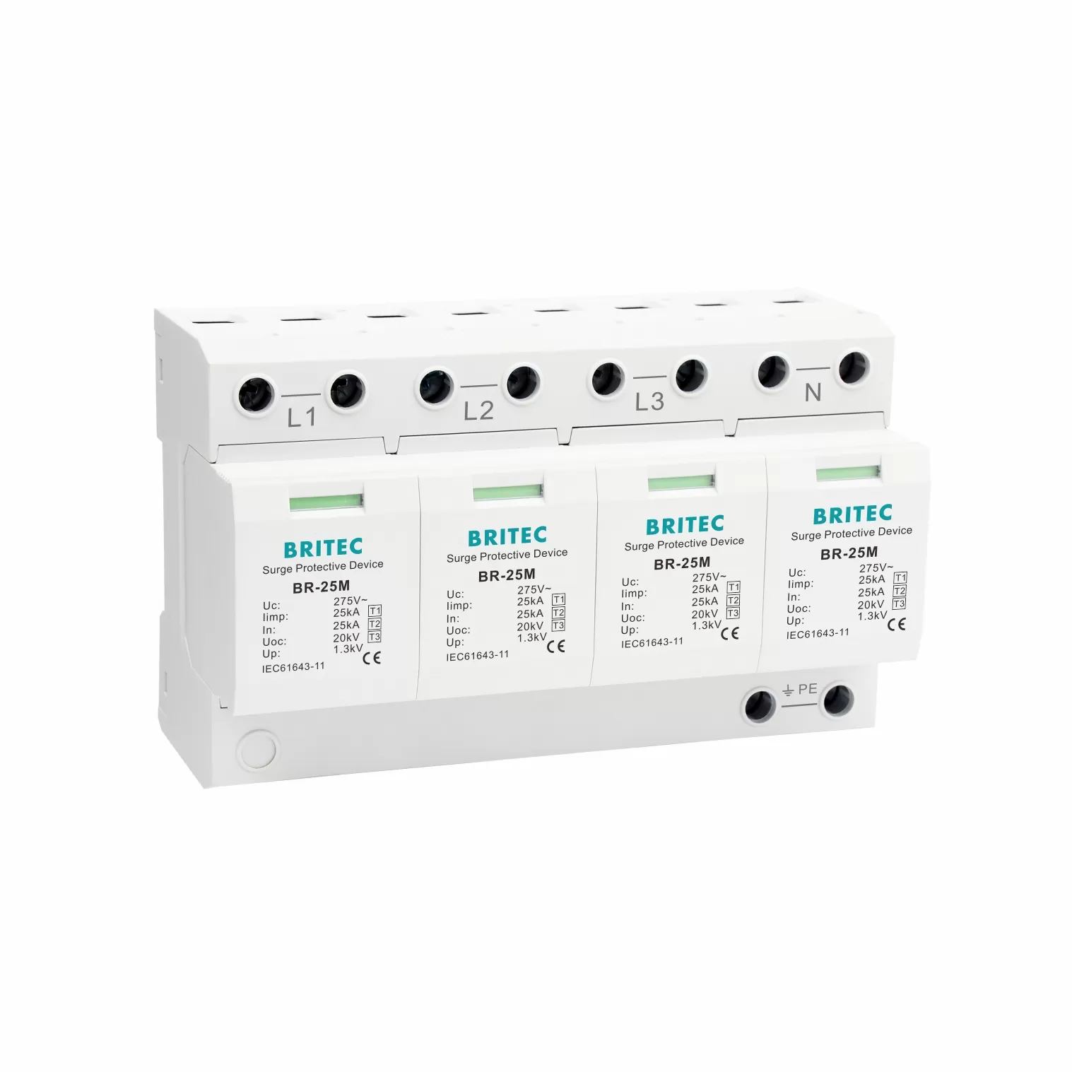
For example, our company’s SLP40-275/3S+1 Type 2 SPD is rated at:
Uc = 275 V AC
In = 20 kA
Imax = 40 kA
Up ≤ 1.5 kV
This makes it ideal for residential, commercial, and industrial distribution boards, as well as UPS protection.
Installing an SPD means working inside a live distribution panel. Safety is non-negotiable.
Disconnect the power completely at the main breaker.
Verify with a tester that all conductors are de-energized.
Apply Lockout/Tagout (LOTO): Use lockout devices and tags to prevent accidental re-energization.
Wear PPE: Insulated gloves, protective glasses, safety shoes.
Check the earthing system: Ensure your PE bar is properly bonded and resistance meets standards (≤10 Ω in most jurisdictions).
Important: Local regulations (IEC 60364, BS 7671, NEC, or your national code) may require installation by a licensed electrician. Always comply with local standards.
Type 2 SPD module (e.g. SLP40-275/3S+1)
DIN rail mounting space inside the panel
Copper conductor: ≥6 mm² for Type 2 SPDs (IEC recommendation)
Proper torque screwdriver or insulated wrench
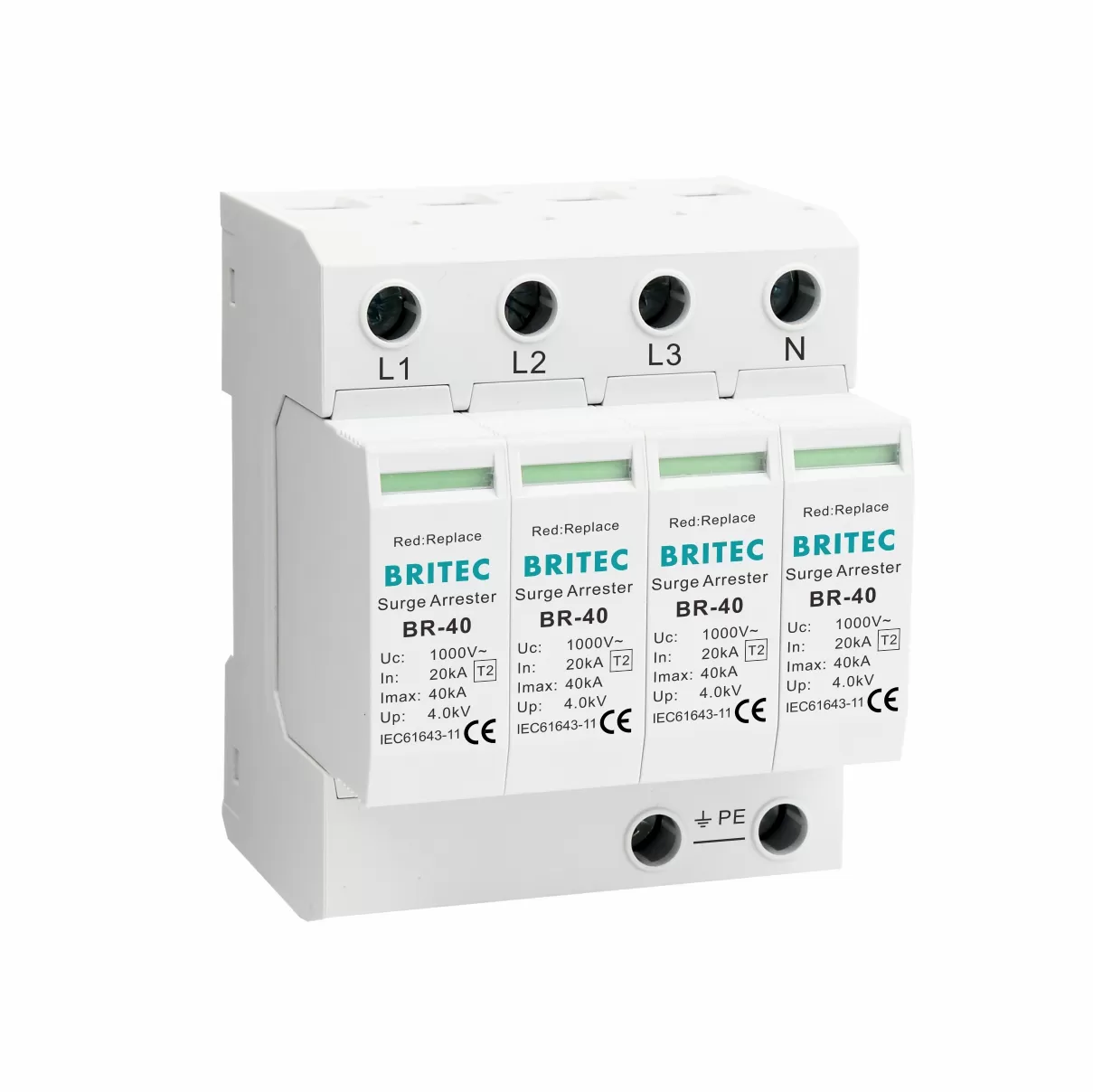
Backup protection device: MCB/fuse, or choose SPD with built-in backup fuse (e.g. BR-30FU series)
Insulation tester & multimeter
Earth bonding strap
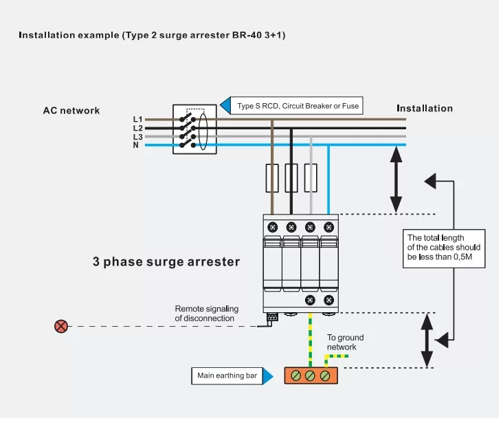
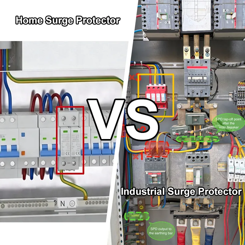
Where: Type 2 SPD must be installed in the main distribution board or on the input side of the UPS system. This location allows it to intercept switching surges and induced lightning transients before they reach sensitive loads.
Why: Installing the SPD too far downstream increases the residual surge voltage (Up) seen by equipment.
Best Practice:
Keep the total conductor length (phase → SPD → earth) ≤ 0.5 m.
Place SPD modules as close as possible to the busbars (L, N, PE).
If the distance between upstream Type 1 and this Type 2 SPD is <10 m, add a decoupling inductor (per IEC 60364) to ensure proper energy coordination.
Ensure the distribution board is fully de-energized. Verify with a multimeter or voltage detector on all incoming phases and neutral.
Check that the DIN rail is securely fastened, clean, and free of corrosion.
Leave adequate space around the SPD for ventilation and future maintenance.
Tip from field practice: Always mount modular SPDs vertically when possible. This supports natural heat dissipation and makes the indicator windows easier to inspect.
Proper wiring is critical, as poor connections can completely compromise surge protection.
Conductor Size:
Type 2 SPD (residential/commercial): ≥ 6 mm² copper.
Type 1 SPD (at service entrance): ≥ 16 mm² copper.
Connection Order:
Connect phase conductors (L1, L2, L3) to the SPD input terminals.
Connect neutral (N) if required by the SPD type (4P or 3+1).
Connect earth (PE) directly to the earth bar with the shortest possible conductor.
Torque: Tighten terminals according to manufacturer datasheet (typically 2.5–3.5 Nm for 6 mm² Cu). Loose terminals create heating and arcing risks.
Why short leads matter: Every 10 cm of wire length adds approximately 1 kV of residual surge voltage. That means long or coiled leads can raise Up beyond equipment tolerance.
Common mistake: Running the PE wire parallel to phase wires over long distances. This increases inductive coupling and weakens protection.
Why needed: An SPD is connected in parallel to the system. If it fails due to severe surge exposure, it may short-circuit. A dedicated backup protective device ensures safe disconnection without tripping the main breaker.
Options:
Standard SPD: Connect via MCB (20–32 A typical for residential) or fuse, rated according to the SPD’s In and Imax.
Integrated solution: Use SPDs with built-in backup fuses (e.g., our BR-30FU series), which eliminates the need for an external protective device.
Standards: IEC 61643 and BS 7671 both recommend selective coordination between SPD and upstream breakers to avoid nuisance tripping.
Direct Path to Earth: The SPD’s earth terminal must be bonded directly to the PE bar. Do not daisy-chain through other devices.
Earth Resistance: According to IEC 60364, grounding resistance should generally be ≤10 Ω, with ≤1 Ω preferred in data centers and telecom facilities.
Equipotential Bonding: Make sure all metal enclosures and cable shields are bonded at the same potential to prevent dangerous potential differences during surges.
Tip: Use flat conductors or braided copper when possible for PE, as they have lower inductance compared to round conductors.
Before re-energizing the system, verify the installation thoroughly:
Visual Inspection:
Confirm all connections are correct (L/N/PE).
Verify conductor lengths are as short as possible.
Check torque on each terminal.
Insulation Test:
Perform insulation resistance tests between L–N, L–PE, N–PE to ensure wiring integrity.
Power-Up Check:
Switch on power and observe the status indicator window on the SPD:
Green = operational
Red = module has failed and must be replaced
Remote Signaling Test (if available):
For SPDs with remote contacts, verify alarm integration with BMS/SCADA systems.
Documentation:
Record SPD type, model number, rated parameters (Uc, In, Imax, Up), installation date, and circuit location for future maintenance.
Featured Snippet Candidate (Summary Style):
To install a Type 2 surge protector, disconnect power and mount it on the DIN rail inside the distribution board. Connect L/N/PE conductors using ≥6 mm² copper with ≤0.5 m total length, add a backup fuse or MCB, and ensure direct earthing to the PE bar. After tightening to the correct torque, perform insulation tests, check the status indicator, and document the installation.
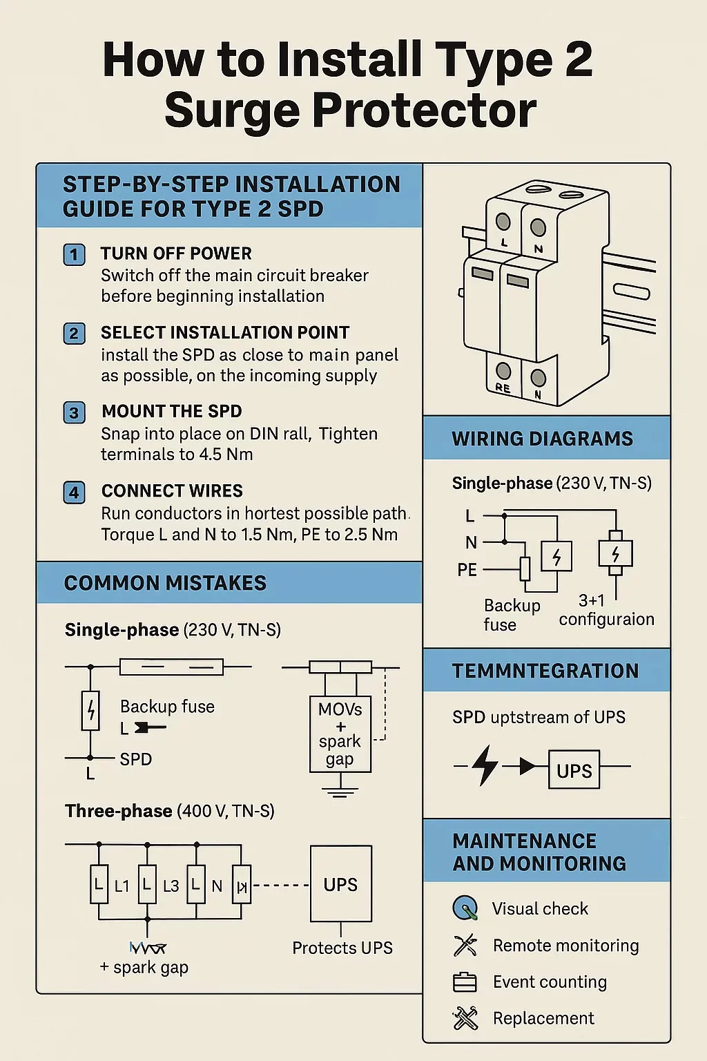
Configuration:
Connect the SPD between L and N, and between N and PE.
For TT systems, ensure the N-PE protection path uses a spark gap or a MOV+GDT combination to avoid continuous leakage currents.
Backup Protection:
A dedicated fuse or MCB must be installed on the phase conductor (L) feeding the SPD branch.
Typical residential setup: 20–32 A MCB rated according to SPD’s In/Imax.
Why it matters: Without proper backup protection, an SPD failure may cause a permanent short circuit, tripping the main breaker and cutting power to the entire installation.
Configuration:
SPD connected across L1-PE, L2-PE, L3-PE, N-PE.
Recommended 3+1 configuration: MOVs across each phase to neutral (L1-N, L2-N, L3-N), plus a spark gap between N and PE.
Advantages of 3+1 configuration:
Reduces residual voltage between neutral and earth.
Provides better coordination in TT and TN-S systems where neutral displacement can occur.
Backup Protection:
Typically, 32–63 A MCBs are required for each SPD branch in industrial/commercial systems.
Professional tip: When protecting three-phase UPS or motor loads, always verify short-circuit current rating (Isc) of the SPD matches the fault level at the distribution point (IEC 61643-11 requirement).
Placement: Install the Type 2 SPD upstream of the UPS rectifier. This ensures surges from the utility grid are clamped before reaching the UPS electronics.
Why upstream, not downstream:
Downstream installation may cause nuisance tripping, since UPS inverters can generate harmonics and fast switching transients.
Upstream placement protects rectifiers, DC capacitors, and inverter modules, extending UPS life.
Example with our products:
SLP40-275/3S+1 upstream of a double-conversion UPS ensures surge currents up to 40 kA are safely diverted, preventing stress on inverter IGBTs and batteries.
Engineering note: In critical IT or healthcare facilities, consider combining Type 1 + Type 2 cascade at UPS input for lightning + switching surge protection.
Mistake: SPD connected with >0.5 m total conductor length.
Why wrong: Each 10 cm adds ~1 kV to the residual voltage (Up). Sensitive electronics (rated 1.5 kV withstand) may still be destroyed.
Best practice: Keep SPD as close as possible to busbars; use straight runs, avoid loops and sharp bends.
Mistake: Using wires <6 mm² Cu for Type 2 SPDs.
Consequence: Excessive heating, risk of insulation breakdown during large surges.
Best practice:
Type 2 SPD → ≥6 mm² Cu (IEC 60364).
Type 1 SPD → ≥16 mm² Cu.
Use low-inductance conductors (braided or flat copper if possible).
Mistake: Directly connecting SPD without MCB/fuse.
Consequence: If SPD fails in short-circuit mode, it can trip the main breaker, shutting down the whole facility.
Best practice:
Always install a dedicated breaker/fuse.
Use SPD models with built-in fuses (e.g. our BR-30FU series) for simplified installation.
Mistake: High resistance ground (>30 Ω) or long parallel routing with phase conductors.
Consequence: Surge current cannot be safely discharged, raising touch voltages and risking equipment/people.
Best practice:
Ensure ground resistance ≤10 Ω (IEC 60364).
In data centers/hospitals, aim for ≤1 Ω.
Connect SPD earth terminal directly to PE bar with shortest conductor.
Mistake: Installing only Type 2 SPDs without Type 1 (for direct lightning) or Type 3 (for terminal equipment).
Consequence: Type 2 alone cannot absorb high-energy lightning currents or protect delicate end devices.
Best practice: Follow the cascade principle (Type 1 + Type 2 + Type 3), ensuring coordination distance ≥10 m or use decoupling inductors if <10 m.
A surge protector is not “install and forget.” Continuous monitoring ensures reliability.
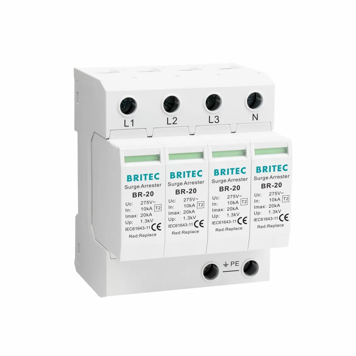
Most SPDs feature a status window (green = operational, red = failed).
Inspect monthly, or after known lightning events.
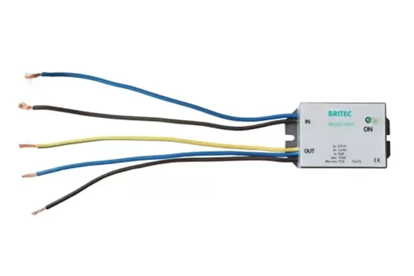
SPDs with remote signaling contacts (NO/NC) can be wired into a building management system (BMS).
This allows facility managers to get alarms if an SPD has failed, even if the panel is not physically inspected.
Use surge counters like BRSC-01 to log each surge event.
Records help in predictive maintenance—if an SPD has handled multiple high-energy events, plan for replacement before failure.
Modular SPDs (like our SLP and BR series) are plug-in/plug-out designs.
Replace the cartridge without rewiring the base—minimizing downtime.
Perform insulation resistance test between conductors.
Measure earth resistance annually (target ≤10 Ω or per local code).
Document test results for compliance audits and warranty records.
Installing a Type 2 surge protector is not complicated, but it must be done correctly. By following proper installation rules—short wiring, correct conductor size, reliable earthing, and backup protection—you ensure that your SPD performs exactly as designed.
A UPS alone is not enough to protect sensitive systems. Pairing it with a properly installed Type 2 SPD provides the resilience modern facilities demand.
Our company’s SLP40-275/3S+1 and BR-30FU series SPDs are designed for easy DIN-rail installation, built-in safety features, and compliance with IEC 61643 standards. Whether you’re protecting a residential board, a commercial office, or an industrial UPS system, these solutions ensure long-term reliability and peace of mind.
 Optimized by Seraphinite Accelerator