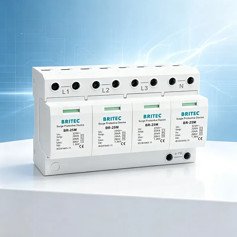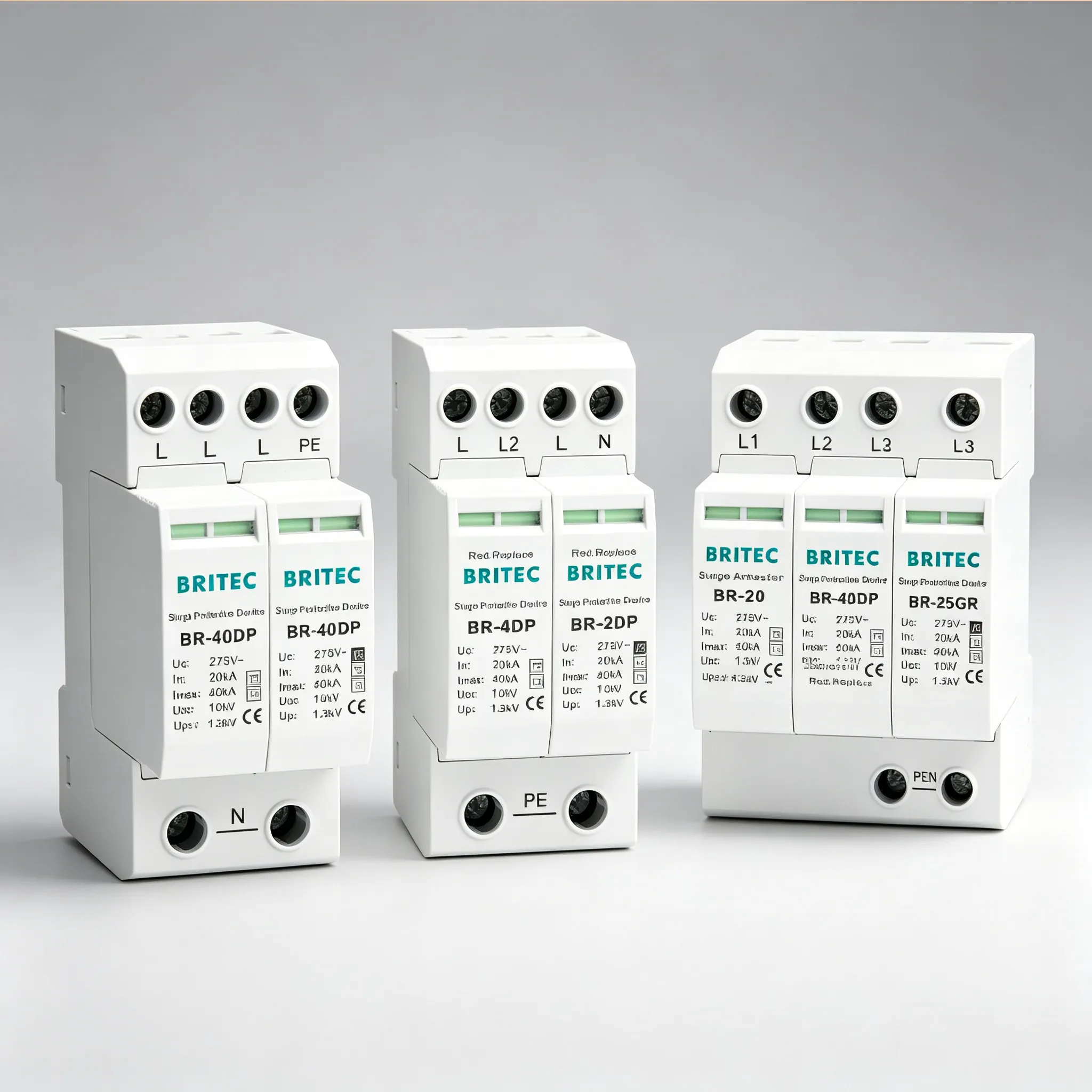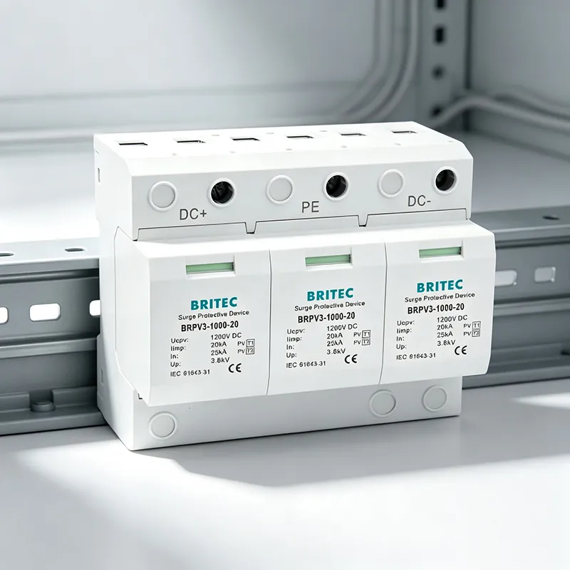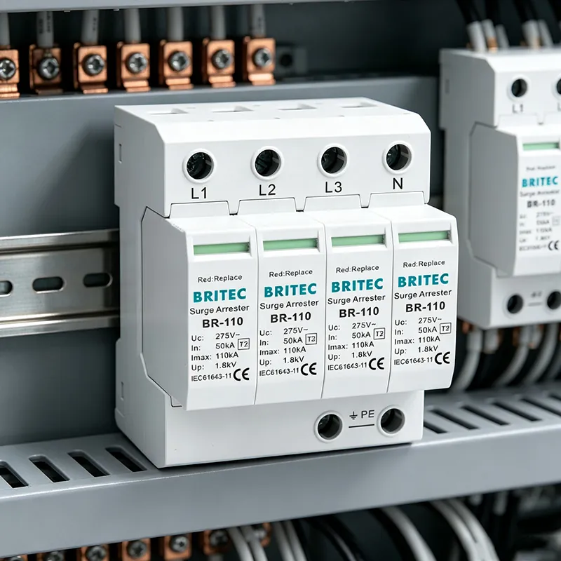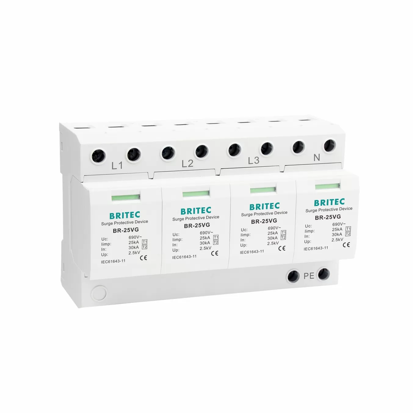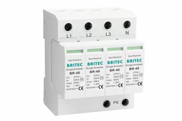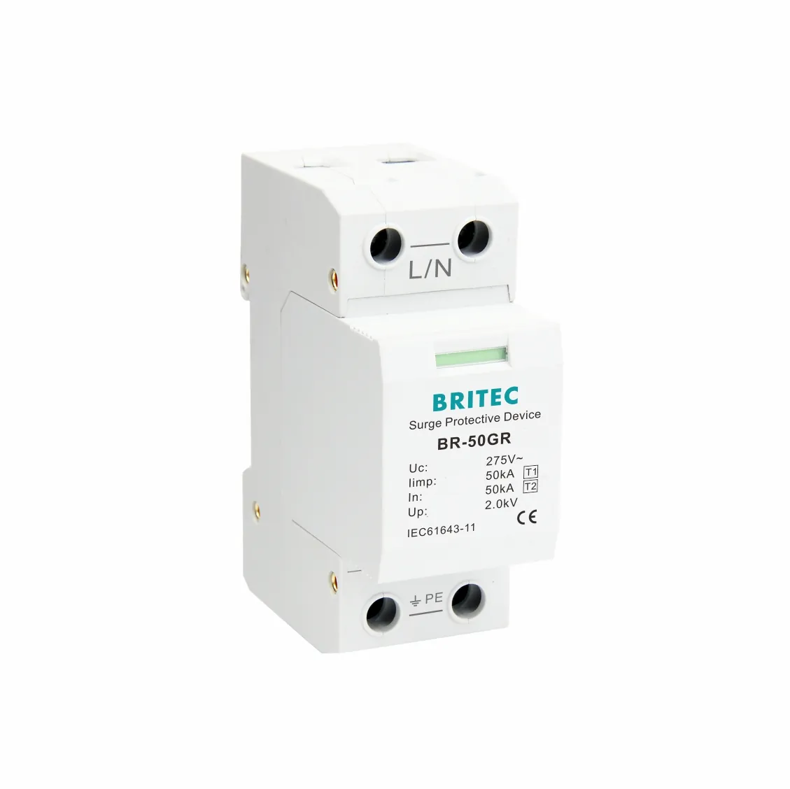

A surge protective device does not destroy a surge. It diverts transient energy safely into the earth. That single fact is why industrial SPD grounding design matters more than almost any other installation detail. A high-quality SPD mounted on a poor ground bar can perform worse than a modest SPD on a clean, low-impedance earth connection. For plant engineers and EPC contractors, grounding is the difference between a protected drive and a silent production line after the next storm.
This guide walks through the grounding and bonding rules that determine real-world SPD performance, the differences between Type 1, Type 1+2, and Type 2 devices, and the mistakes that quietly cancel out your protection. It is written for buyers and specifiers who need practical, standards-based direction rather than marketing language.
When lightning or a switching transient hits an incoming feeder, the SPD clamps the voltage and gives the current a low-resistance path to earth. Two numbers decide the outcome. The first is the clamping voltage of the SPD. The second is the impedance of the path from the SPD to the ground electrode. If that path is long, thin, or routed near other cables, the effective let-through voltage at the protected equipment rises, and the SPD cannot do its job.
In short, the SPD and the ground are one system. You cannot specify one without designing the other. This is the core idea behind every SPD earthing recommendation in IEC 62305 and IEC 61643-12.
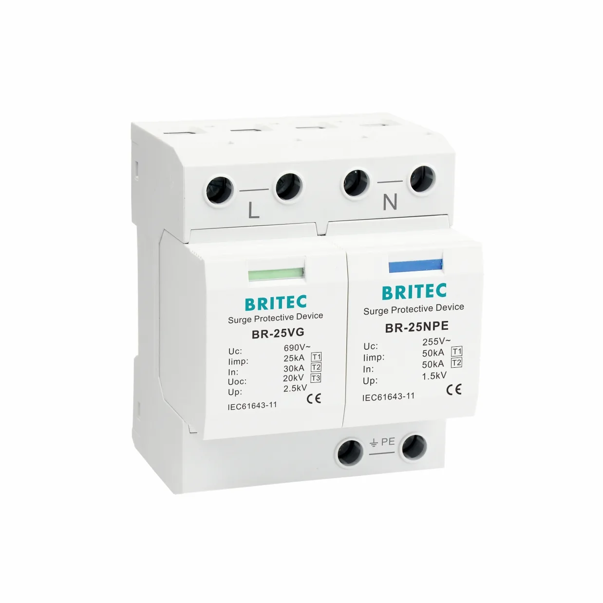
The following checks apply to almost every industrial site, from switchgear rooms to solar inverter stations and pump houses. Treat them as a baseline before you finalize any SPD layout.
The earth connection is the foundation. A ground rod driven into dry or rocky soil, or a thin conductor bonded to painted steel, gives the surge nowhere to go. Aim for a tested earth resistance that meets your local code and the equipment manufacturer limit, and verify it with a clamp-on earth tester after installation.
● Use a dedicated ground electrode — a driven rod, ground ring, or foundation electrode sized for the available soil conditions.
● Measure, do not assume — document the earth resistance value so future maintenance has a baseline.
ال SPD grounding conductor size must carry the expected surge current without heating or voltage drop. Undersized wire is a common failure point. Follow the cross-section minimums given in IEC 61643-12 and your national wiring rules, and remember that a short, thick conductor beats a long, thin one every time.
● Match the conductor to the SPD Imax — higher current ratings need larger cross-sections.
● Keep the same metal — copper-to-aluminum transitions need proper lugs to avoid corrosion.
Every extra centimeter of grounding lead adds inductance, and inductance resists the fast front of a lightning surge. Route the SPD ground lead directly to the ground bar with the fewest bends possible. Coiling excess cable beside the SPD is a classic mistake that raises let-through voltage.
Equipotential bonding SPD practice means connecting all metallic parts — panel enclosures, cable trays, machine frames, and the SPD ground — to the same potential during a surge. Separate, unconnected grounds let a voltage difference appear between structures and damage sensitive electronics. Bond everything that a surge can reach.
The protected equipment and the SPD share the same grounding point only when the SPD is mounted near the incoming service or the load. Long downstream runs between SPD and equipment erode protection. This is why main-incoming Type 1 and Type 2 devices sit at the distribution board, not far down the line.
If the building has an external lightning protection system, the SPD grounding must integrate with it, not fight it. Type 1 devices are specifically designed to handle direct lightning currents and should connect to the lightning protection equipotential bonding network.
Data and control cables nearby can pick up the surge if their grounds form a loop with the power earth. Keep signal cable trays separated from the SPD ground run, and use coordinated data-line protectors where sensitive instruments are present.
Ground resistance changes with seasons and soil moisture. A grounding design that passed commissioning can drift out of spec within a year. Build periodic earth-resistance and SPD status checks into your maintenance plan so protection does not silently degrade.
The device type changes what the ground must absorb. Type 1 SPD grounding handles partial direct lightning currents and connects to the lightning protection bonding network. Type 2 SPD grounding handles induced and switching surges at the distribution board. Type 1+2 combines both roles in one enclosure for buildings where the external LPS and internal surges arrive together.
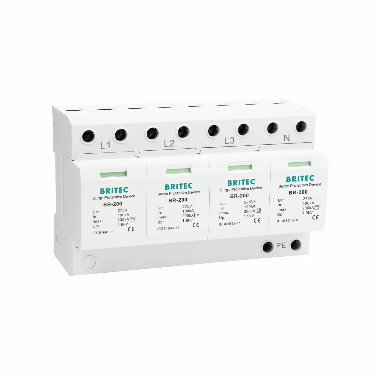
For most industrial main panels, a Type 2 device backed by a clean ground bar is the workhorse, while exposed or tall structures add a Type 1 stage at the service entrance. The right combination depends on your incoming risk, not on a single product. Review surge protection coordination guidance to cascade the stages correctly.

● Sharing a loosely bonded structural steel — painted or bolted frames are not a ground path.
● Long, coiled ground leads — inductance defeats the clamping action.
● Undersized conductors — heating and voltage rise under surge current.
● Missing equipotential bond — voltage differences damage connected electronics.
● Never re-testing earth resistance — soil drift silently weakens protection.
Each of these maps to a real field failure. Our common SPD failure causes article shows how grounding errors show up as burned modules and tripped loads.
Use this table as a commissioning reference. A clean pass on every row is the practical definition of a well-grounded SPD installation.
| Design Check | What To Verify |
|---|---|
| Ground electrode | Documented earth resistance within code and SPD limit |
| Conductor size | Cross-section meets IEC 61643-12 for the SPD Imax |
| طول الرصاص | Short, straight run with no coils or excess slack |
| Equipotential bond | Enclosures, trays, and frames bonded to one point |
| SPD location | Mounted at service entrance or near the load |
| Type coordination | Type 1, Type 1+2, or Type 2 matched to risk |
| Re-test plan | Scheduled earth-resistance and status inspection |
Need A Grounding-Safe SPD Layout For Your Plant?
Britec engineers help EPC contractors and factory buyers select Type 1, Type 1+2, and النوع 2 SPD models and specify the grounding that makes them work. Send your single-line diagram and we will review it.
Why is grounding critical for SPD effectiveness?
A surge protective device only works if the diverted current has a fast, low-impedance path to earth. A poor ground raises let-through voltage at the equipment and can leave the SPD unable to clamp the transient. Grounding and the SPD are one system, not two separate items.
What size grounding conductor should I use for an industrial SPD?
The cross-section must match the SPD rated surge current and your national wiring rules, with IEC 61643-12 as the common reference. Larger Imax ratings require thicker conductors. When in doubt, size up and keep the run short rather than thin and long.
Can SPD grounding share the building main earthing electrode?
Yes, in most installations the SPD connects to the same main earthing terminal as the rest of the equipotential bonding network. The key is a solid, low-resistance bond to that point, not a separate isolated ground which would create a dangerous voltage difference.
How long should the SPD grounding conductor be?
As short and straight as practical, ideally well under one meter at the service entrance. Inductance in a long lead resists the fast surge front, so route directly to the ground bar and never coil spare cable beside the device.
What is the difference between equipotential bonding and grounding for SPD?
Grounding connects the system to the earth electrode. Equipotential bonding connects all nearby metal structures to the same potential during a surge so no damaging voltage appears between them. Effective SPD protection needs both working together.
Which SPD type needs the most careful grounding, Type 1 or Type 2?
Type 1 devices handle partial direct lightning currents and must bond into the lightning protection system, so their grounding is the most demanding. Type 2 devices manage induced and switching surges at the distribution board and rely on the same clean main earth.
What standards apply to SPD grounding design?
The most referenced are IEC 62305 for lightning protection, IEC 61643-11 and IEC 61643-12 for SPD selection and installation, and IEC 62561 for earthing components. National wiring codes add local requirements on top of these.
How do I verify SPD grounding after installation?
Measure earth resistance with a clamp-on or three-pole tester, confirm the bond torque and continuity from the SPD to the ground bar, and record the values. Repeat on a maintenance schedule because soil conditions change with the seasons.
● How SPD Surge Protective Devices Handle Transient Overvoltage
● When Should You Use A 4 Pole Surge Protection Device
● Industrial Surge Protection Device: 7 Ways Surges Damage Plants
● Type 1 Surge Protection Device FAQ: 10 Most Asked Questions
Talk To A Britec SPD Specialist
Specifying the right SPD is only half the work. Get your grounding design reviewed by our engineering team before procurement.