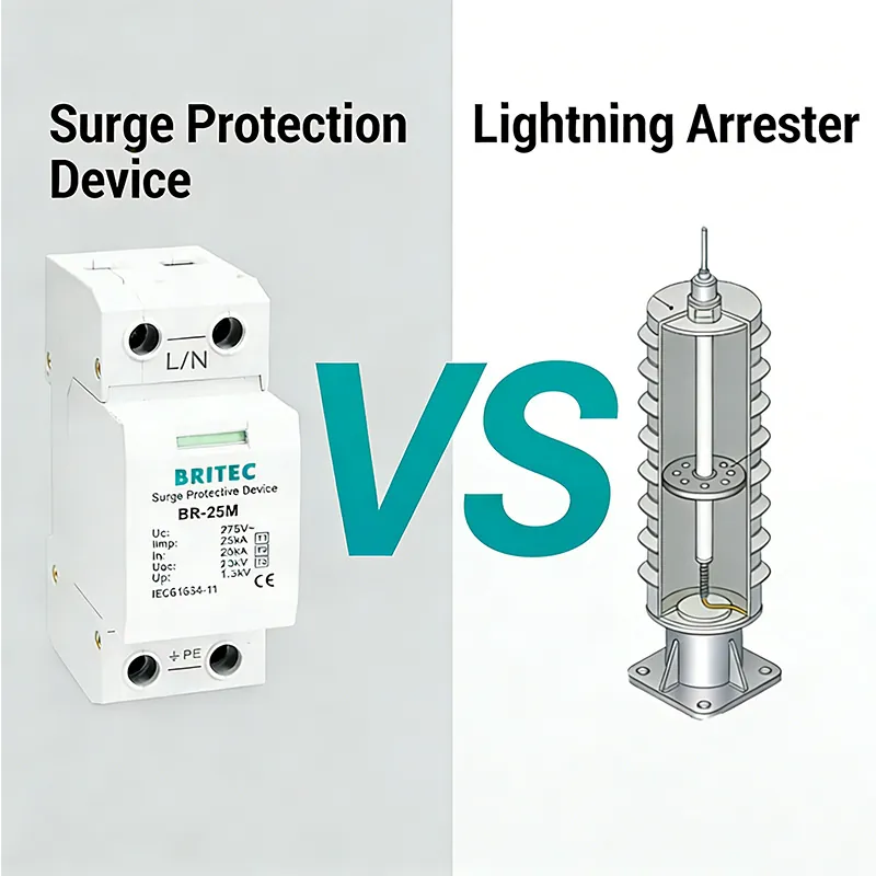
Surges are one of the most underestimated threats in electrical systems. A sudden overvoltage, whether caused by lightning, grid switching, or even internal equipment, can degrade insulation, trip breakers, or destroy sensitive devices in an instant. A Single-Phase Surge Protection Device (SPD) is the first line of defense. It diverts excess energy to earth and ensures that the voltage reaching your equipment stays within safe limits.
For electrical engineers and procurement specialists, the challenge is not whether to use a single phase SPD, but how to choose the right one. This guide provides a clear, technical, and practical approach that combines international standards, engineering best practices, and real-world experience.
A Single-Phase Surge Protection Device is installed in 230/240V single-phase AC systems to guard against transient overvoltages. It operates by remaining passive under normal voltage, but as soon as a surge occurs, it becomes a low-impedance path and redirects the surge current to the ground.
Single phase protection devices are widely applied in residential distribution boards, commercial buildings, solar photovoltaic systems, and industrial control panels. In each case, they extend the lifetime of equipment, reduce downtime, and provide compliance with modern safety requirements.
The selection of a surge protection device single phase must be aligned with international standards, primarily IEC 61643-11 and IEC 61643-12. These define the testing waveforms, classification, and installation guidelines:
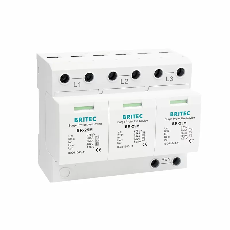
Type 1 SPD: Tested with 10/350 µs waveform, designed to withstand direct lightning currents. Installed at the service entrance where overhead lines or lightning protection systems are present.
Type 2 SPD: Tested with 8/20 µs waveform, protects against switching surges and indirect lightning. Typically installed in distribution panels.
Type 3 SPD: Installed close to sensitive loads, ensures very low residual voltage (Up). Used as the last stage of protection.
If you want a deeper dive into the detailed classification of SPDs and how each type is defined in standards and practical applications, you can explore our dedicated article here: Classification of SPDs.
When comparing different single phase SPDs, several parameters are critical for proper selection:
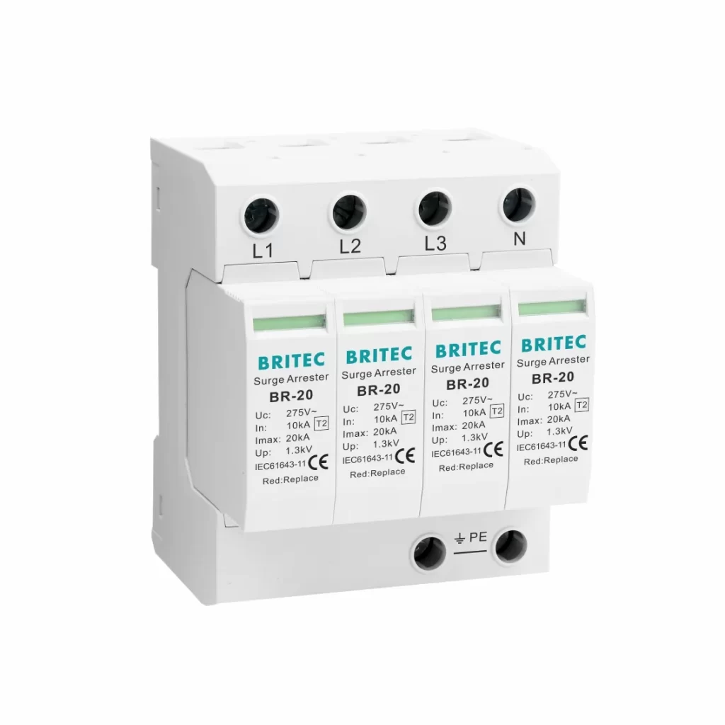
Uc (Maximum Continuous Operating Voltage): The maximum RMS voltage the device can handle without degradation. For 230/240V systems, the standard value is 275V AC between line and neutral.
Up (Voltage Protection Level): The clamped voltage during a surge. Sensitive electronics require Up below 1.5–2.5 kV.
In (Nominal Discharge Current): The current the SPD can discharge repeatedly without failure. A good single-phase SPD should handle at least 20 kA (8/20 µs).
Imax (Maximum Discharge Current): The maximum current the SPD can withstand in a single event, typically 40 kA or more.
Iimp (Impulse Current): Specific for Type 1 SPDs, tested with 10/350 µs waveform. Values start at 12.5 kA, with 25 kA recommended in high-risk areas.
Response Time: SPDs act in nanoseconds. The faster the reaction, the better protection for sensitive electronics.
These parameters should always be matched with the system’s exposure level, earthing type, and equipment insulation category.
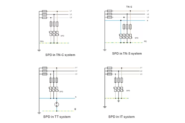
Earthing type is often overlooked, but it is one of the most decisive factors when choosing a Single-Phase Surge Protection Device.
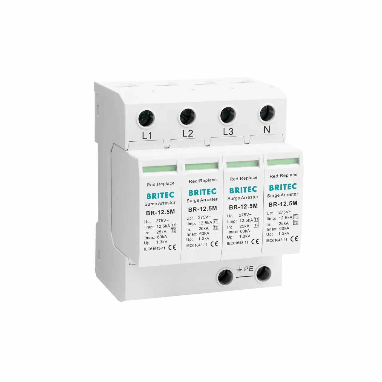
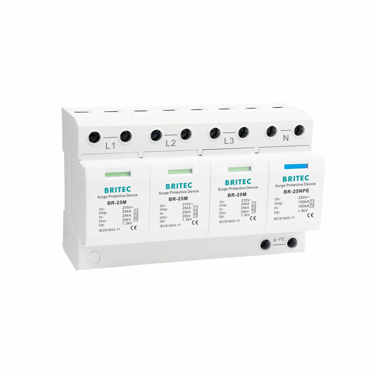
TT Systems: Require 1P+N (also called 1+1) SPD. This configuration uses MOV protection between line and neutral, plus a spark gap or dedicated element between neutral and PE. It ensures controlled discharge to earth, which is vital in TT where neutral potential can rise during faults.
TN-S or TN-C-S Systems: Can use either 1P or 1P+N depending on the design of the distribution board. Both line-to-neutral and line-to-earth paths must be protected.
TN-C Systems: Usually apply 1P or 2P SPDs depending on whether the PEN conductor is accessible.
For all systems, wiring rules remain the same: keep the SPD’s connection to earth as short as possible, ideally less than 0.5 m. Long leads increase inductance and therefore increase the residual voltage that the protected device will see.
This is the heart of the decision-making process. Many engineers and buyers search specifically for how to choose a single phase SPD, so this section provides a detailed, practical roadmap:
Determine whether the building has an external lightning protection system (LPS) or is supplied by overhead lines. If yes, a Type 1 SPD at the service entrance is mandatory. For underground supplies in low-risk areas, a high-capacity Type 2 may be sufficient.
Check whether your installation is TT, TN-S, TN-C-S, or TN-C. This determines if you need a 1P SPD, a 1P+N SPD, or a 2P SPD. Selecting the wrong wiring configuration can render the SPD ineffective.
At the service entrance: Type 1 or Type 1+2 combined SPD.
At distribution panels: Type 2, with In ≥ 20 kA and Imax ≥ 40 kA.
At sensitive loads: Type 3, to reduce Up below the insulation withstand of electronic devices.
Match the SPD’s ratings to your system:
Uc: 275V AC for 230/240V systems.
Up: Must be lower than the equipment insulation category (IEC 60664: Cat II ≈ 2.5 kV, Cat III ≈ 4 kV).
In/Imax/Iimp: According to installation level and risk zone.
SPDs must work together. The upstream device must absorb energy without passing destructive voltage downstream, while the downstream SPD fine-tunes protection. Maintain at least 10 meters between devices, or insert decoupling inductance to ensure proper energy sharing.
Every SPD requires backup protection. Unless the SPD includes an integrated fuse, install an MCB or fuse in series. This prevents short-circuit events when the SPD reaches end of life.
SPDs degrade over time. Choose models with:
Status indication windows that show green/red conditions.
Remote signaling contacts for monitoring in control systems.
Replaceable plug-in modules, so maintenance does not require rewiring.
Following this step-by-step process ensures that your single phase SPD is not only correctly rated but also correctly installed and maintained for long-term reliability.
Even the best single phase protection devices will fail if installed incorrectly. Follow these engineering principles:
Keep leads short and direct, less than 0.5 m.
Separate power and signal cables to avoid coupling surges.
Do not bundle SPD leads with protected circuits.
Always connect the SPD earth to the closest equipotential bonding bar.
Respect the coordination distances between different SPD stages.
Common mistakes include installing only one stage, forgetting N-PE protection in TT systems, or oversizing SPDs without actual need. Each of these reduces protection efficiency and increases costs without benefit.
Residential Applications: A Type 2 SPD (In 20 kA, Imax 40 kA, Up < 1.5 kV) installed in the main distribution board protects household electronics from grid disturbances.
Commercial Buildings: A Type 1+2 SPD at the main switchboard combined with Type 2 SPDs at floor distribution panels ensures continuity of service.
Industrial Facilities: Type 1 SPDs rated at 25 kA Iimp at the service entrance, with coordinated Type 2 SPDs in motor control centers and Type 3 SPDs protecting PLCs.
Solar PV Systems: On the DC side, use PV-rated SPDs. On the AC side, a Type 2 single-phase SPD at the inverter output protects both the inverter and the grid interface.
Choosing the right Single-Phase Surge Protection Device requires more than scanning a datasheet. It means understanding your system, evaluating risks, applying IEC standards, and matching parameters carefully.
At the entrance, protect against lightning with Type 1.
In distribution, rely on robust Type 2 devices.
For sensitive electronics, add Type 3 at the point of use.
Always respect your earthing system, wiring practices, and maintenance needs.
By applying these principles, electrical engineers and procurement professionals can ensure that their systems are not only compliant but also resilient, cost-effective, and future-ready.
 Optimized by Seraphinite Accelerator