Caratteristiche del prodotto:
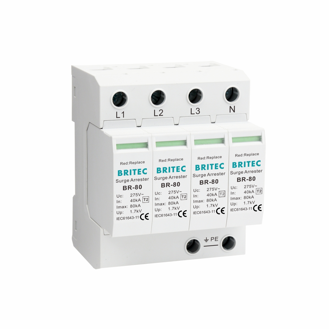
| Specifica | BR-801504P | BR-80 275 4P | BR-80 320 4P | BR-80 385 4P | ||
| Classificazione SPD secondo EN61643-11 | Tipo 2 | Tipo 2 | Tipo 2 | Tipo 2 | ||
| Classificazione SPD secondo IEC61643-11 | Classe II | Classe II | Classe II | Classe II | ||
| Massimo. funzionamento continuo c.a. voltaggio | Uc | 150 V | 275 V | 320 V | 385 V | |
| Corrente di scarica nominale (8/20μs) | In | 40kA | 40kA | 40kA | 40kA | |
| Massimo. corrente di scarica (8/20μs) | Imax | 80kA | 80kA | 80kA | 80kA | |
| Livello di protezione della tensione | Su | ≤1,0 kV | ≤1,7kV | ≤2,0 kV | ≤2,3kV | |
| Livello di protezione dalla tensione 5kA | Su | ≤0,6 kV | ≤1,0 kV | ≤1,1kV | ≤1,2kV | |
| Massimo. fusibile di riserva | 160A gG | 160A gG | 160A gG | 160A gG | ||
| Capacità di tenuta al cortocircuito | Isccr | 25kA | 25kA | 25kA | 25kA | |
| Resistenza TOV a sovratensione temporanea | UT | 180 V/5 secondi. | 335 V/5 sec. | 400 V/5 secondi. | 500 V/5 secondi. | |
| Guasto TOV-safe per sovratensione temporanea | UT | 230 V/120 min. | 440 V/120 min. | 520 V/120 min. | 650 V/120 min. | |
| Tempo di risposta | tA | ≤25ns | ≤25ns | ≤25ns | ≤25ns | |
| Intervallo di temperatura operativa | Tu | -40℃-80℃ | -40℃-80℃ | -40℃-80℃ | -40℃-80℃ | |
| Indicazione dello stato di funzionamento/guasto | verde/rosso | verde/rosso | verde/rosso | verde/rosso | ||
| Area della sezione trasversale (Min.) | 4mm² | 4mm² | 4mm² | 4mm² | ||
| Area della sezione trasversale (max.) | 35 mm² | 35 mm² | 35 mm² | 35 mm² | ||
| Per il montaggio | Guida DIN da 35 mm | |||||
| Materiale della custodia | Termoplastico UL94-V0 | |||||
| Grado di protezione | IP20 | IP20 | IP20 | IP20 | ||
| Codice ordine | B18260 | B18262 | B18264 | B18266 | ||
| Codice d'ordine (Con segnalazione remota) | B18261 | B18263 | B18265 | B18267 | ||
Caratteristiche:
Visualizzazione visiva dello stato
Connessioni etichettate
Tipo 2 (classe II/C) per quadri principali, quadri di distribuzione e centralini.
Disponibili con e senza contatti di segnalazione remota.
Da 1 polo fino a 4 poli protetti.
BR-80 è costituito da un blocco varistore ad alte prestazioni con dispositivo di disconnessione termica. Il design del modulo/base plug-in facilita la sostituzione di un modulo guasto in situ senza la necessità di rimuovere il cablaggio del sistema.
Soluzioni conformi alle norme IEC 61643-1 ed EN 61643-11
Applicazione:
Quadro elettrico di distribuzione situato a valle di uno scaricatore di corrente da fulmine di Tipo 1.
Proteggendoli dagli impulsi diretti e indiretti dei fulmini e da altre sovratensioni transitorie.
Protegge i sistemi a bassa tensione dalle sovratensioni innescate da fulmini o operazioni di commutazione della rete.
Ideale per applicazioni industriali.
All'origine dell'impianto elettrico nel quadro principale, in aree in cui sono dominanti i campi elettromagnetici causati dalle correnti di fulmine (escluso un colpo diretto).
Adatto per sistemi TN-S.
Prevenire la diffusione della sovratensione media (Up) nell'impianto elettrico e proteggere le apparecchiature ad esso collegate.

Ulteriori informazioni o una consulenza personale? I nostri prodotti e il nostro know-how sono lì per fornire soluzioni.
 #!trpst#trp-gettext data-trpgettextoriginal=901#!trpen#Optimized by #!trpst#trp-gettext data-trpgettextoriginal=900#!trpen#Acceleratore serafinite#!trpst#/trp-gettext#!trpen##!trpst#/trp-gettext#!trpen#