Caratteristiche del prodotto:
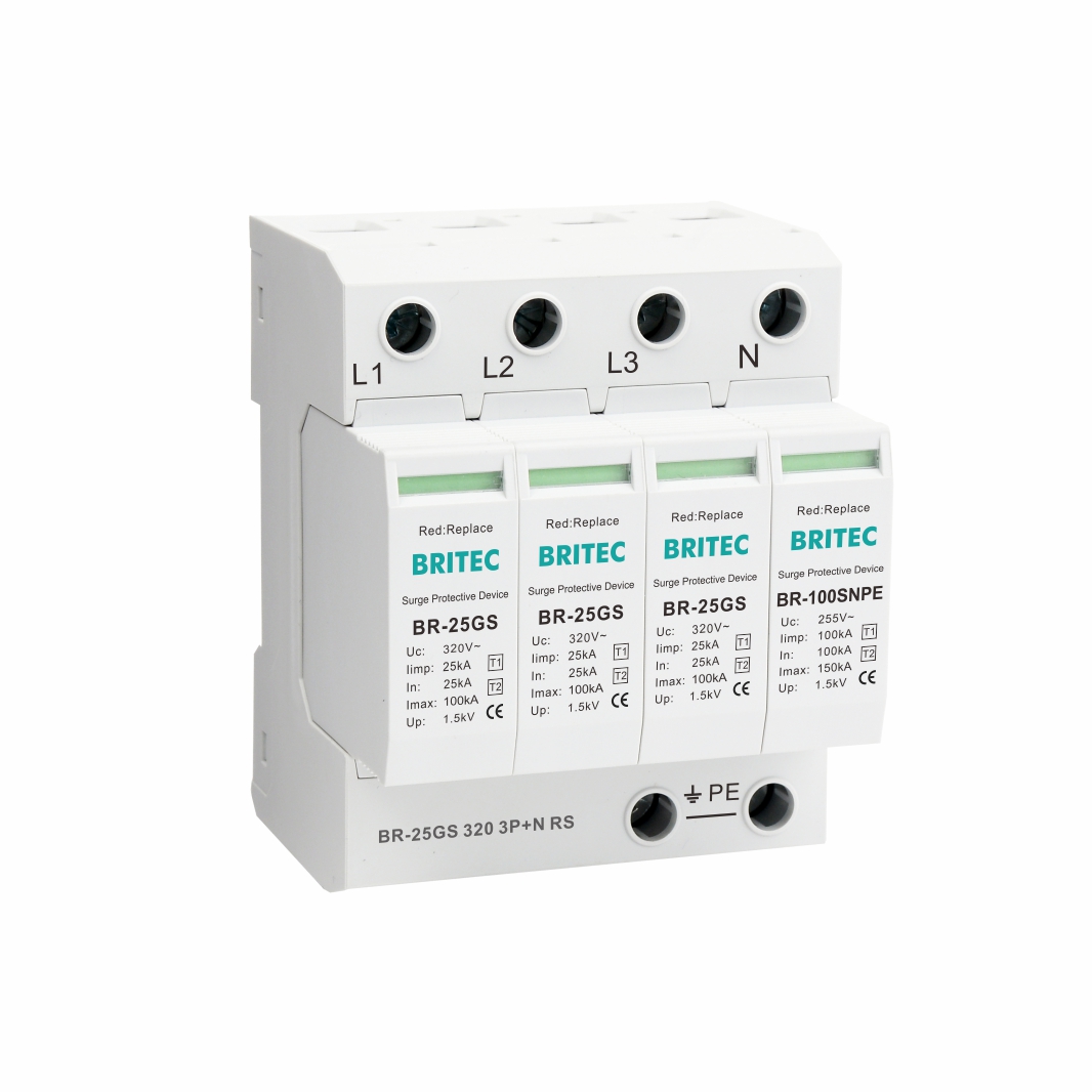
| Specifica | BR-25GS150 3P+N | BR-25GS 275 3P+N | BR-25GS 320 3P+N | |
| Classificazione SPD secondo EN61643-11 | Tipo 1 + Tipo 2 | Tipo 1 + Tipo 2 | Tipo 1 + Tipo 2 | |
| Classificazione SPD secondo IEC61643-11 | Classe I + Classe II | Classe I + Classe II | Classe I + Classe II | |
| Corrente nominale in c.a. voltaggio | Un | 120 V/240 V (50/60 Hz) | 230 V/400 V (50/60 Hz) | 240 V/415 V (50/60 Hz) |
| Massimo. funzionamento continuo c.a. voltaggio | Uc (L-N/N-PE) | 150 V/255 V (50/60 Hz) | 275 V/255 V (50/60 Hz) | 320 V/255 V (50/60 Hz) |
| Corrente impulsiva di fulmine (10/350μs) | Iimp (L-N/N-PE) | 25kA/100kA | 25kA/100kA | 25kA/100kA |
| Corrente di scarica nominale (8/20μs) | Dentro (L-N/N-PE) | 25kA/100kA | 25kA/100kA | 25kA/100kA |
| Massimo. corrente di scarica (8/20μs) | Imax (L-N/N-PE) | 100kA/150kA | 100kA/150kA | 100kA/150kA |
| Quantità di carica elettrica (L-N, N-PE) | Q (L-N/N-PE) | 12,5 A/50 A | 12,5 A/50 A | 12,5 A/50 A |
| Energia specifica (L-N, N-PE) | W/R (L-N/N-PE) | 156kJ/Ω, 2500kJ/Ω | 156kJ/Ω, 2500kJ/Ω | 156kJ/Ω, 2500kJ/Ω |
| Livello di protezione della tensione | Su (L-N/N-PE) | ≤1,5kV/≤1,5kV | ≤1,5kV/≤1,5kV | ≤1,5kV/≤1,5kV |
| Massimo. fusibile di riserva | 200A gG | 200A gG | 200A gG | |
| Corrente nominale di cortocircuito c.a. | Isccr | 25kA | 25kA | 25kA |
| Seguire la capacità di estinzione attuale c.a. | Ifi (L-N/N-PE) | 25 kA/100 A | 25 kA/100 A | 25 kA/100 A |
| Resistenza TOV a sovratensione temporanea | UT (L-N) | 230 V/120 min. | 440 V/120 min. | 580 V/120 min. |
| Resistenza TOV a sovratensione temporanea | UT (N-PE) | 1200 V/200 ms | 1200 V/200 ms | 1200 V/200 ms |
| Tempo di risposta | tA | ≤100ns | ≤100ns | ≤100ns |
| Corrente di dispersione | Ipe | <0,1 mA | <0,1 mA | <0,1 mA |
| Intervallo di temperatura operativa | Tu | -40℃-85℃ | -40℃-85℃ | -40℃-85℃ |
| Indicazione dello stato di funzionamento/guasto | verde/rosso | verde/rosso | verde/rosso | |
| Area della sezione trasversale (Min.) | 4mm² | 4mm² | 4mm² | |
| Area della sezione trasversale (max.) | 35 mm² | 35 mm² | 35 mm² | |
| Per il montaggio | Guida DIN da 35 mm | |||
| Materiale della custodia | Termoplastico UL94-V0 | |||
| Grado di protezione | IP20 | IP20 | IP20 | |
| Codice ordine | B17058 | B17071 | B17096 | |
| Codice d'ordine (Con segnalazione remota) | B17059 | B17072 | B17097 | |
| Suffissi: aggiungere il suffisso “RS” per la versione con segnalazione remota a contatto pulito. Esempio: BR-25GS 275 3P+N RS | ||||
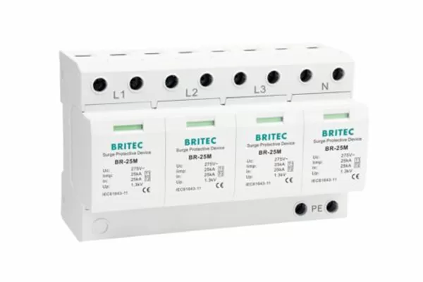
Caratteristiche:
Tipo: protezione da sovratensione T1+T2
Tempo di risposta: ≤100ns
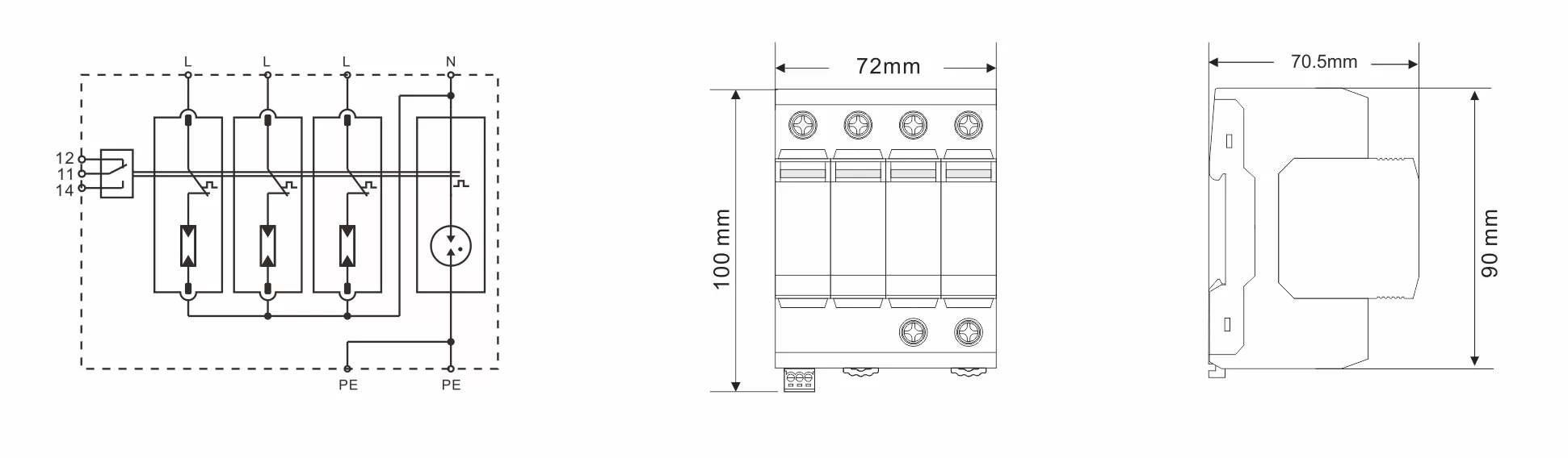
Connessioni etichettate.
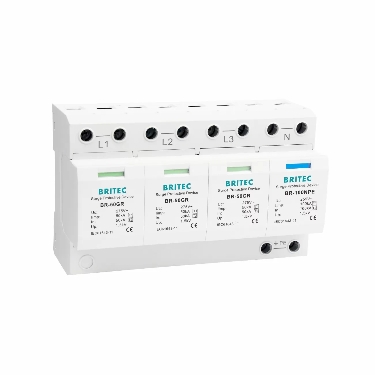
Tipo composito: 3P+N.
Installazione: binario standard 35mm.
Progettato per proteggere gli impianti elettrici a bassa tensione dalle sovratensioni elettriche causate da azioni di commutazione, fulmini e impulsi elettromagnetici.
Secondo IEC61643-11.
Dispositivo di disconnessione termica.
Collegamento con terminale a vite.
Applicazione:
Protegge gli impianti elettrici dai fulmini diretti e scarica la corrente di ritorno generata dai fulmini che si propagano dal conduttore di terra ai conduttori di rete.
Il dispositivo è progettato per essere utilizzato tra la Zona O e la Zona 1 (secondo la definizione IEC 62305-4 dell'area di protezione dai fulmini).
Può essere utilizzato per proteggere il sistema di alimentazione trifase.
Le questioni richiedono attenzione quando si installa SPD:
Determinare il percorso della corrente di scarica.
Contrassegnare i fili che producono un'ulteriore caduta di tensione sul terminale del dispositivo.
Contrassegnare il conduttore PE di ciascun dispositivo per evitare circuiti induttivi non necessari.
Viene stabilita una connessione equipotenziale tra il dispositivo e l'SPD.
Durante l'installazione, collegare il dispositivo secondo lo schema di installazione, dove L è la linea di fase, N è la linea neutra e PE è la linea di terra. Non collegare in modo errato il dispositivo.
Ulteriori informazioni o una consulenza personale? I nostri prodotti e il nostro know-how sono lì per fornire soluzioni.
 #!trpst#trp-gettext data-trpgettextoriginal=901#!trpen#Optimized by #!trpst#trp-gettext data-trpgettextoriginal=900#!trpen#Acceleratore serafinite#!trpst#/trp-gettext#!trpen##!trpst#/trp-gettext#!trpen#