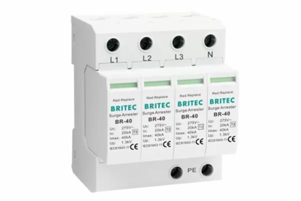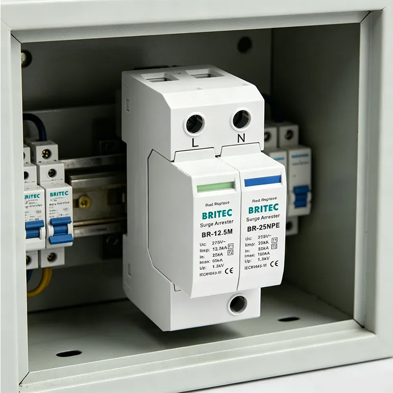

A 50kA surge protector at end of life looks exactly like one still doing its job. Same module, same position on the rail, same clean housing. The only difference is a small window that has turned from green to red, and the fact that everything behind it is now unprotected.
Most 50kA devices do not fail because they were poorly made. They fail because something in the specification or the installation put them under stress the datasheet never assumed. Five mechanisms account for the large majority of field failures, and each one has a straightforward prevention.
Surge protectors are consumables. Every event they divert consumes a measurable share of their capacity, and the process is one-way — nothing restores a device to its original condition.
How that consumption shows up depends on the technology. Varistor-based devices degrade continuously: leakage current creeps upward, the disc runs warmer, and the clamping voltage drifts. Spark-gap devices such as Britec’s BR-50GR series degrade through electrode erosion, holding their characteristics well until they approach the end of their operating life. The BR-50GR carries a charge quantity of 25 As and specific energy of 625 kJ/Ω per pole, which is a large reserve — but a reserve nonetheless.
Prevention is inspection rather than specification. Read the status window after every significant storm, and on installations where nobody checks the board regularly, order the version with a remote signalling contact so the device reports its own condition.
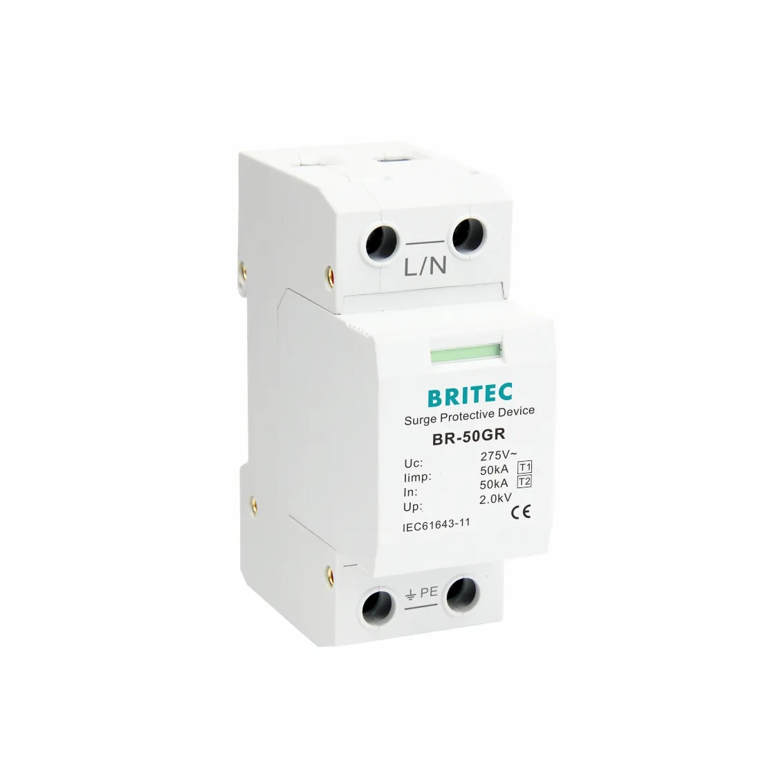
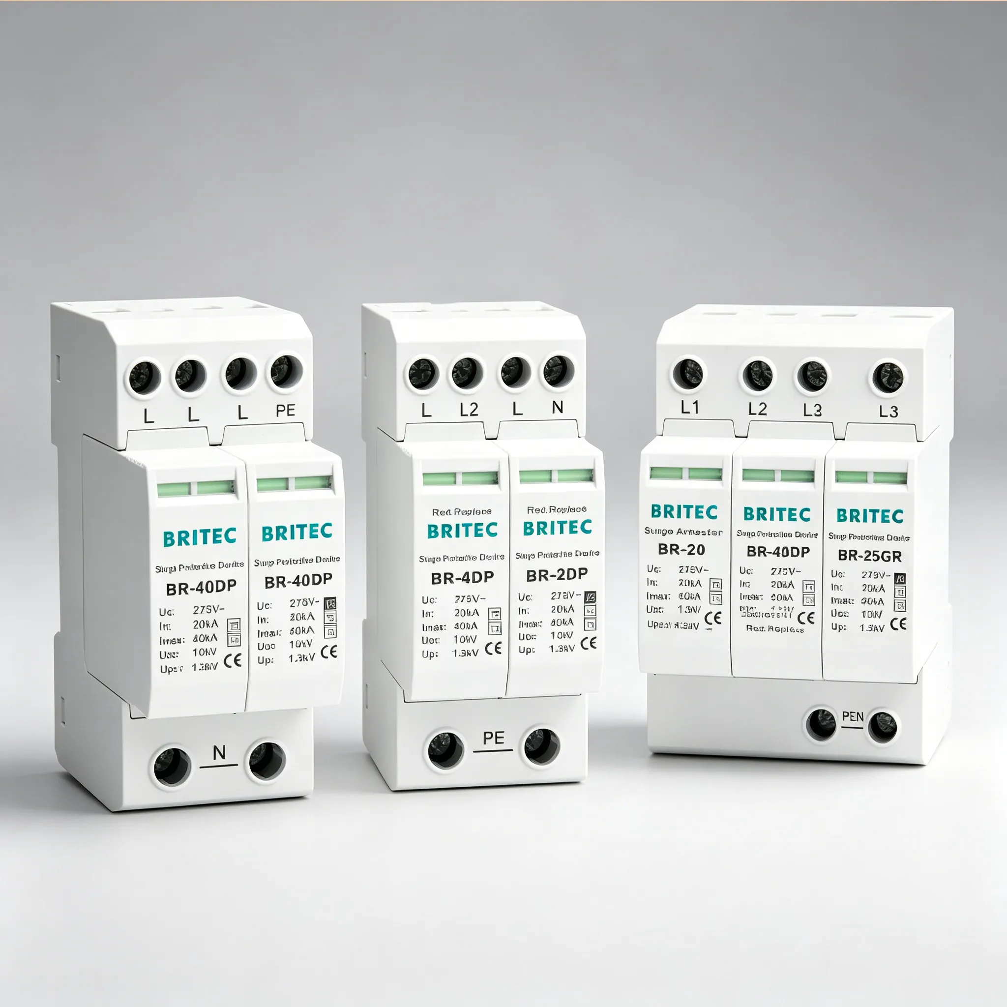
The BR-50GR rated Iimp 50kA on 10/350 µs, with a green/red status window and optional remote signalling contact for unattended boards.
Uc is the maximum continuous operating voltage the device tolerates without conducting. Specify it too close to the nominal supply and the protector spends its life on the edge of conduction, drawing leakage current and heating up during every routine overvoltage on the network.
This is the failure that arrives early and gets blamed on quality. A device sized for a stable 230V supply may be entirely unsuitable on a network with sustained voltage rise from distributed generation or a weak transformer tap. Temporary overvoltage figures make the point: the BR-50GR 275 withstands 440V for 120 minutes, and beyond that its life is being spent, not used.
Prevention is to measure rather than assume. Check the actual supply voltage over time, including the highest sustained excursion, and select Uc with headroom — the BR-50GR is available in 150V, 275V and 350V versions for exactly this reason.
Every surge protector fails toward a short circuit. As the internal element degrades, leakage rises, heating increases, and heating accelerates leakage — a runaway that ends in a low-resistance path across your supply unless the thermal disconnect intervenes first.
The disconnect is a solder-held spring contact that releases at a defined temperature, isolating the device and flipping the status window to red. It fails to keep up in two situations: when the device has been operating close to its Uc limit for a long period, so degradation is faster than the design assumed, and when ambient temperature inside the enclosure is high enough to shift the thermal margin. The BR-50GR is rated for −40°C to +80°C, which is generous, but a sealed cabinet in direct sun can still approach it.
Prevention is enclosure discipline: ventilate boards carrying high-energy devices, avoid mounting SPDs directly beside heat-generating equipment, and treat any discolouration on the housing as a reason to replace immediately.
When the thermal disconnect operates, the backup fuse or breaker is what safely isolates the device from the supply. Two specification errors defeat it.
The first is exceeding the maximum backup fuse rating. The BR-50GR specifies 315 A gG as the maximum; if the upstream overcurrent device is larger, the SPD circuit is not protected in the failure mode that matters, and a short at end of life becomes a fire risk rather than a controlled disconnection. The second is ignoring the short-circuit current rating. The BR-50GR is rated Isccr 25 kA rms, so if the prospective fault current at the installation point exceeds that figure, the device is unsuitable for that board regardless of how good its discharge ratings look.
Prevention is two checks before ordering: confirm the prospective short-circuit current at the board against the device Isccr, and confirm the existing upstream protection is at or below the maximum backup fuse rating.
This is the most common failure of all, and strictly speaking the device does not fail — the installation does. The BR-50GR publishes a voltage protection level of ≤2.0kV, and that figure is measured at the device terminals, not at your equipment.
Every centimetre of connecting conductor adds inductance, and inductance under a fast-rising surge adds voltage. Long connecting leads on the live and earth sides can add hundreds of volts to what actually reaches the load, so the protection level your equipment sees bears little relation to the datasheet. The equipment fails, the SPD indicator stays green, and the device is judged to have not worked.
Prevention is the 0.5 metre rule: keep the total conductor length on the live and earth sides combined within about half a metre, run the conductors straight rather than looped, and use a V-connection where board layout allows the supply conductors to land directly on the SPD terminals.
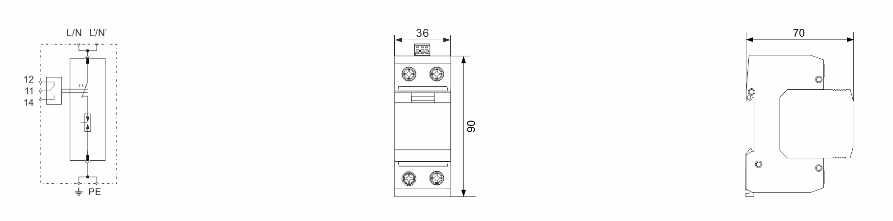
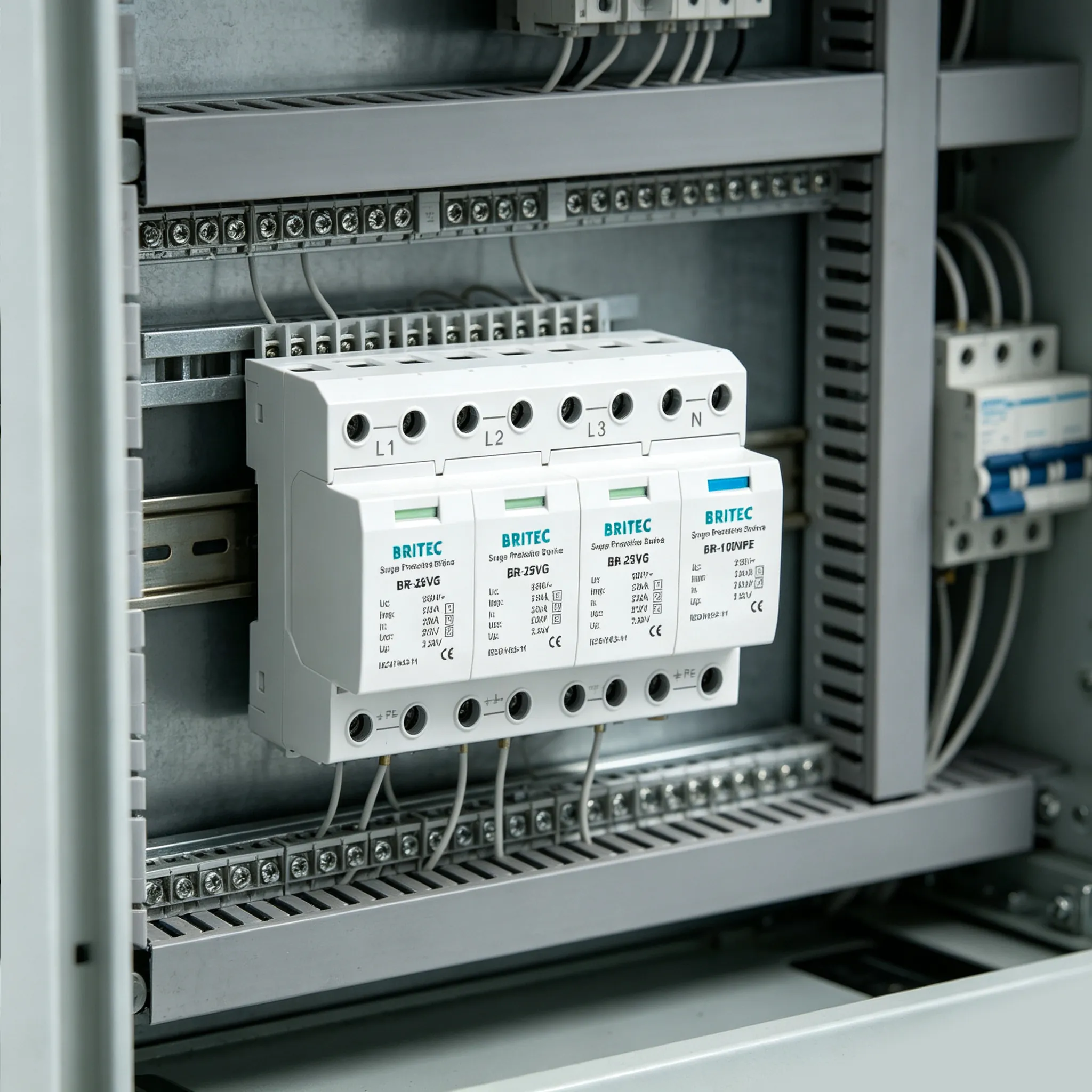
The BR-50GR wiring arrangement — short, direct conductors on both the live and earth sides preserve the ≤2.0kV protection level the datasheet promises.
The table maps each failure mechanism to the symptom it produces on site and the practice that prevents it, using published BR-50GR figures where a specific limit applies.
| Failure Mechanism | Symptom on Site | Prevention |
| Cumulative degradation | Status window turns red; remote contact signals fault | Inspect after storms; specify remote signalling on unattended boards |
| Undersized Uc | Early failure; warm housing; repeated replacements | Measure sustained supply voltage; choose 150V, 275V or 350V version with headroom |
| Thermal runaway | Discoloured or distorted housing; burn marks; tripped backup device | Ventilate the enclosure; keep within −40°C to +80°C; replace on any discolouration |
| Backup fuse or Isccr error | Backup device fails to clear; damage beyond the SPD | Keep upstream fuse at or below 315 A gG; confirm site fault level under 25 kA rms |
| Excessive lead length | Equipment damaged while SPD indicator stays green | Total lead length under 0.5 m; straight runs; V-connection where possible |
The fifth row deserves particular attention, because it is the only failure that produces no evidence at the device. A protector showing green after an equipment loss is usually taken as proof the surge came from elsewhere. Far more often it means the connecting leads let through what the device itself had clamped.
Six checks cover all five mechanisms and take a few minutes each.
Before ordering, confirm the prospective short-circuit current at the installation point against the device Isccr, and measure the supply voltage over a working period so Uc is chosen with real headroom rather than from the nominal figure. Confirm the upstream overcurrent device is at or below the maximum backup fuse rating.
During installation, plan conductor routing before terminating anything so total lead length stays under half a metre, and check that the enclosure has adequate ventilation and no adjacent heat source. After commissioning, set an inspection interval — monthly visual checks plus a check after every significant storm — or specify remote signalling if the board is unattended, and record the installation date so age can inform replacement planning.
Britec Electric Wenzhou has manufactured surge protective devices since 2003, with ISO 9001 and ISO 14001 certification, products tested to IEC 61643-11 and UL 1449, and an in-house impulse laboratory so production batches are verified rather than only certification samples.
The BR-50GR series is a spark-gap device classified Type 1+2 / Class I+II, rated Iimp 50kA and In 50kA with Imax 160kA per pole, Up ≤2.0kV, charge quantity 25 As and specific energy 625 kJ/Ω. It is available in 150V, 275V and 350V versions, assembles from 1P into 2P, 3P and 4P arrangements, and combines with the BR-100NPE to form 1P+N and 3P+N configurations for TT systems. Every version offers a green/red status window, an optional remote signalling contact, a thermal disconnection device, UL94 V-0 housing and 4–35 mm² terminals on 35 mm DIN rail.
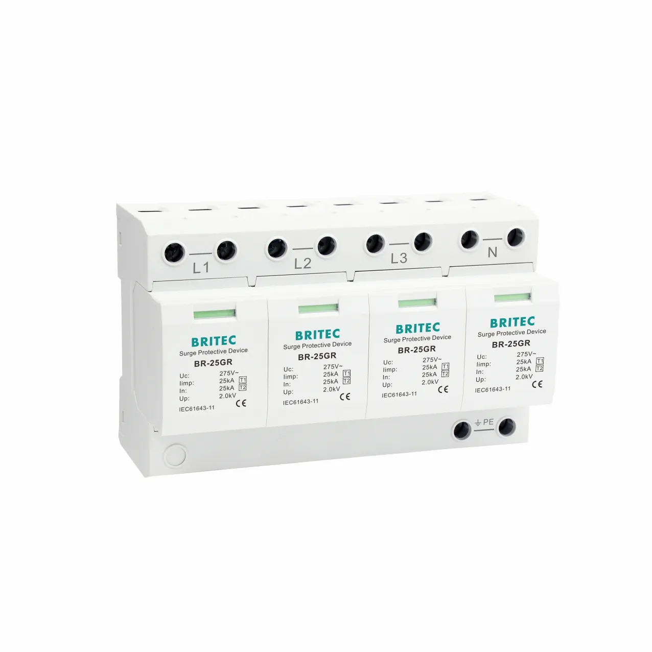
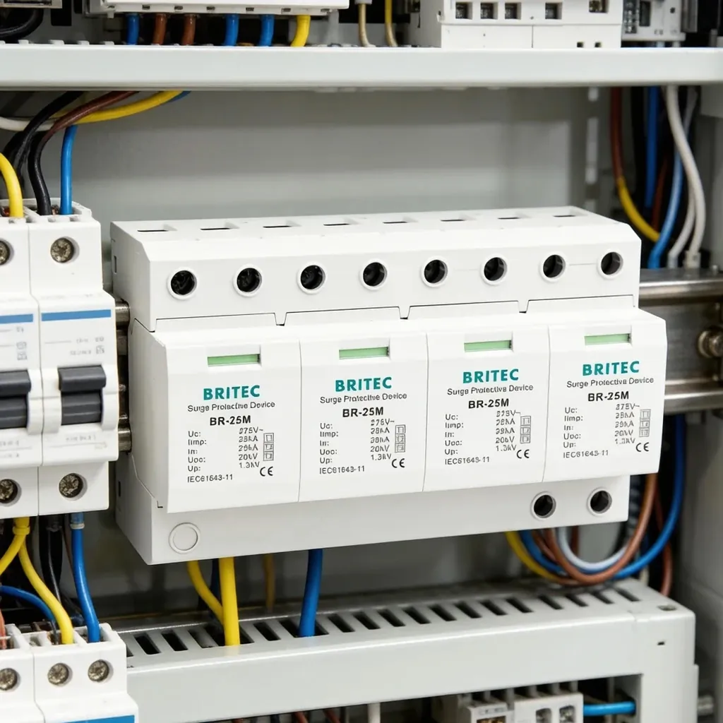
The same GR platform in a 4P arrangement — the series spans 25kA and 50kA Iimp across 1P to 4P and 3P+N configurations.
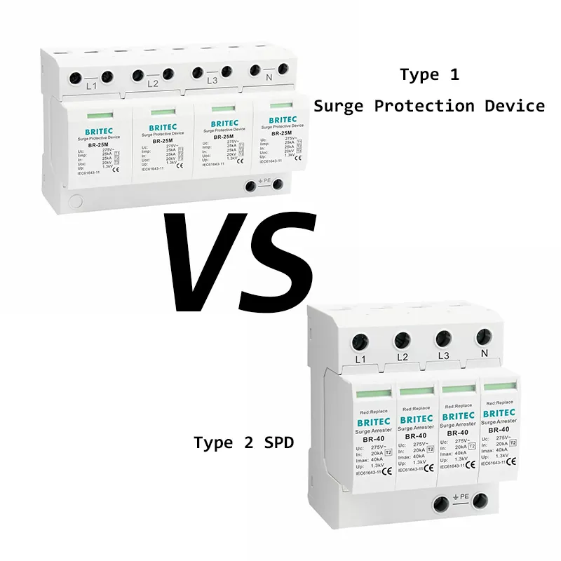
It depends entirely on which rating the 50kA refers to. Britec’s BR-50GR is classified Type 1+2 / Class I+II with Iimp 50kA on the 10/350 µs waveform — a lightning current arrester for the service entrance. Other products advertised as 50kA are Type 2 devices quoting Imax 50kA on 8/20 µs, which is a far smaller energy capability. Always check the classification line and the waveform before comparing.
There is no fixed number, because it depends on the energy in each event rather than the count. A device rated 25 As of charge and 625 kJ/Ω has substantial reserve and will absorb many moderate transients, while a single event near its maximum consumes a large share at once. This is why status indication exists — the window reports condition, which no surge count could.
It handles the partial lightning current conducted into the installation, which is what a service entrance device is designed for. It does not substitute for an external lightning protection system, which intercepts and conducts the strike itself. The two work together: the LPS handles the strike, the Type 1 device handles the share that enters your wiring.
Use the maximum stated on the datasheet — 315 A gG for the BR-50GR series. If the upstream overcurrent device is already at or below that rating, a separate backup is not required. Exceeding it means the SPD circuit is unprotected when the device fails short at end of life.
Read the status window: green means functional, red means the device has disconnected and needs immediate replacement. Also check that the backup fuse or breaker has not operated, and look for discolouration or distortion of the housing. On unattended installations, a remote signalling contact wired into the control system is the only reliable method.
A 50kA surge protector rarely fails because the device was inadequate — with Iimp 50kA, 25 As of charge and 625 kJ/Ω of specific energy, the BR-50GR has ample capability for the duty it is sold for — but it fails readily when Uc is specified from the nominal supply voltage instead of the measured one, when enclosure heat narrows the thermal disconnect’s margin, when the upstream fuse sits above the 315 A limit or the site fault level exceeds the 25 kA Isccr, and above all when connecting leads run longer than half a metre and quietly add hundreds of volts to a ≤2.0kV protection level; check the four specification limits before ordering, plan the conductor routing before terminating, and read the status window after every storm, and the device will do its job for years rather than failing early and being blamed for it. If you are specifying 50kA protection for a project, contact Britec Electric at [email protected] or +86 0577-6260 5321 for datasheets, certificates and a quotation on the Uc version and pole configuration your installation requires — our technical team responds to all enquiries within 24 hours.