
A 4 pole SPD is the workhorse of three-phase surge protection: one module per phase (L1, L2, L3) plus one for the neutral, clamping transient overvoltages on every live conductor of a 230/400 V TN-S or TT distribution board. But a surge protective device is a consumable, not a fit-and-forget component. Its metal-oxide varistors degrade with every surge they divert, and a degraded SPD protects nothing while still looking perfectly normal from the outside. This guide explains how to inspect, test, and replace a 4 pole SPD in a real electrical system – with practical checklists, testing intervals, and failure signs drawn from Britec Electric’s experience manufacturing surge protective devices since 2003. Every procedure below follows IEC/EN 61643-11 practice and is written for panel builders, maintenance contractors, facility managers, and electrical distributors who specify protection for industrial and commercial sites.
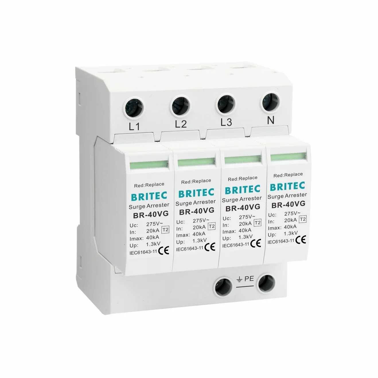
In a three-phase four-wire system (TN-S), a 4 pole surge protective device connects L1, L2, L3, and N to the PE bar through metal-oxide varistors (MOVs). Each pole monitors one conductor, so a fault or degradation on a single phase does not leave the other phases unprotected. When a transient arrives – from lightning-induced coupling, capacitor switching, or a large motor start – the MOVs clamp within nanoseconds and divert the surge current to earth, holding the voltage at the downstream equipment below its impulse withstand level.
● L1 / L2 / L3 poles – clamp phase-to-earth and phase-to-neutral surges on each phase conductor.
● N pole – clamps neutral-to-earth surges, which matter in TN-S systems where neutral floating can push tens of volts onto equipment chassis.
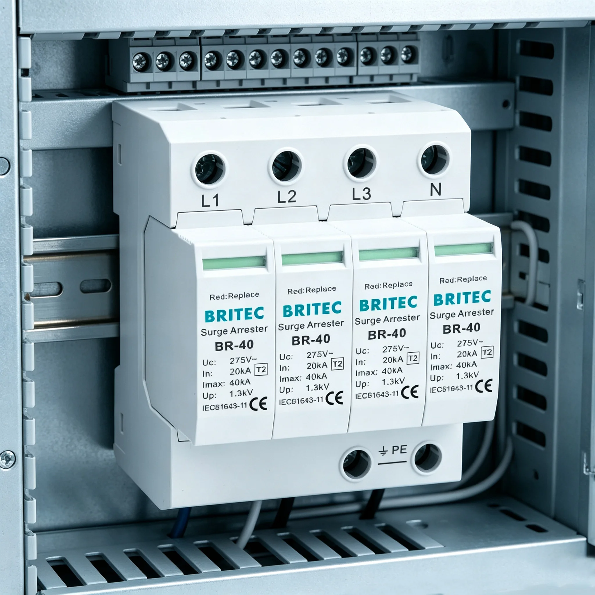
● Status windows – each module carries a visible green/red indicator: green means the varistor is healthy, red means end of life and immediate module replacement.
If you are still deciding whether a four-pole configuration is right for your earthing system, read our guide on when to use a 4 pole surge protection device – the rest of this article assumes the selection is already made and focuses on keeping it operational.
An MOV absorbs surge energy by design, and every absorption event ages it slightly. As the varistor degrades, three things happen progressively: its clamping voltage drifts upward (less protection per surge), its leakage current at normal operating voltage rises (more heat at idle), and its thermal disconnector moves closer to tripping. An SPD that has silently reached end of life offers no clamping at all – the next surge passes straight through to your PLCs, VFDs, meters, and control circuits.
For B2B operators the cost calculus is one-sided. A replacement Type 2 module set costs a fraction of one production stoppage, one lifted HVAC rooftop unit, or one failed EMS controller. Routine maintenance also keeps installations compliant: IEC 60364-5-53 requires that surge protective devices remain serviceable and that their status can be verified, which in practice means documented periodic inspection. Most manufacturers, Britec included, publish an expected service life of three to five years in moderate-exposure locations – less at sites with frequent thunderstorm activity, poor earthing, or heavy switching loads.
Visual inspection is the 80/20 of SPD maintenance: two minutes per board, no shutdown required, and it catches the majority of failed devices. Train your maintenance staff to work through this list with the enclosure door open and the panel energized:
● Check all four status windows. Green on L1, L2, L3, and N means healthy. Any red window – even one – means the affected pole has reached end of life and the module must be replaced (see the replacement section below).
● Look for heat discoloration. Brown or yellowed plastic around the terminals, melted wire insulation, or a burnt smell indicates thermal stress or a loose connection that needs immediate attention.
● Confirm the module is fully seated. Plug-in SPD modules can work loose from vibration. The module body should sit flush against the base with no visible gap on the DIN rail.
● Inspect wiring and terminals. Conductors should be intact, properly ferruled, and free of corrosion. Minimum cross-section is 4 mm² and maximum 35 mm² for most Type 2 devices.
● Check the backup protector. The dedicated fuse or circuit breaker upstream of the SPD (typically 100 A gG for a 40 kA device) must be closed. A tripped backup protector usually means the SPD has disconnected itself after a major event.
● Log the inspection. Record the date, board location, and window status of each pole. Trend data across months is what turns maintenance into prediction.
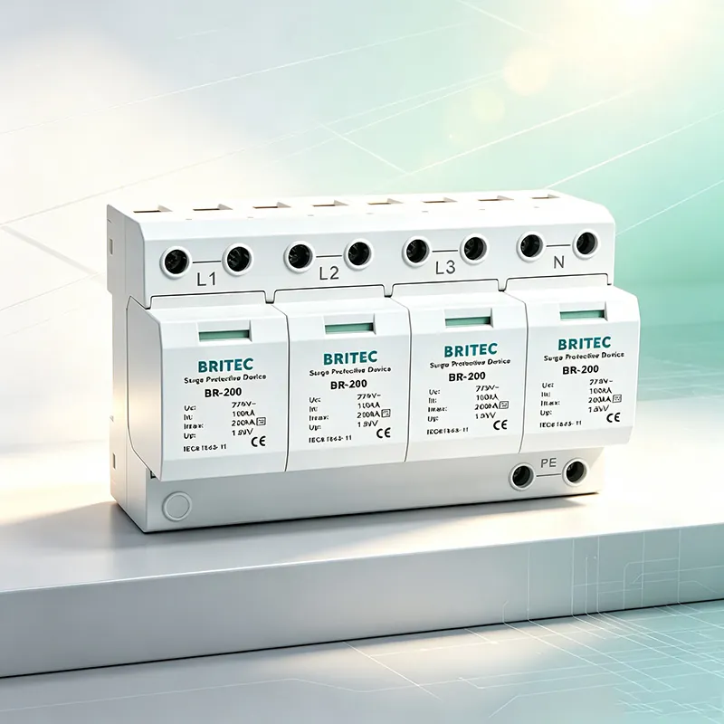
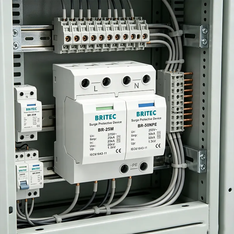
The photo below shows a healthy installed unit: four modules, four green windows, clean terminations on L1, L2, L3, and N. This is what your monthly check should confirm on every board.
A severe thunderstorm can consume a year of normal varistor aging in one multi-stroke flash. After any storm that produced nearby lightning strikes, a utility fault, or visible surges in the building, run the monthly checklist again – especially the status windows and the backup protector. Devices with remote signaling contacts will often report a pre-alarm through the BMS before the window turns red, so cross-check any SCADA or building-management alarms against the panel. Sites in high lightning-density regions (typically more than 25 thunderstorm days per year) should treat post-storm checks as mandatory, not optional.
Once a year – or quarterly in critical facilities such as hospitals, data centers, and continuous-process plants – complement the visual check with instrumented testing during a planned shutdown:
● Terminal re-torque. Thermal cycling loosens terminations. Re-tighten power and earth terminals to the manufacturer’s torque specification and re-seat conductors.
● Thermographic survey. With the panel under normal load, scan the SPD with an infrared camera. A pole running measurably hotter than its siblings is leaking current – replace the module even if its window is still green.
● Earthing continuity. Measure the resistance of the PE connection from the SPD earth terminal to the main earthing bar; it should be well below 0.5 Ω. A corroded earth connection makes every other protection measure irrelevant.
● Remote signaling test. Where the device has a remote-signal contact option, trip the contact manually (or use the test lever if fitted) and confirm the alarm appears at the BMS/SCADA end. For a deeper instrument-based procedure, see our guide on how to test an industrial surge protection device.
● Record-keeping review. Update the asset register with module age, surge events logged, and any replacements. This history determines the right replacement interval for your specific site rather than a generic one.
Need a maintenance-friendly SPD for your panel project?
Britec’s Type 2 devices feature green/red status windows, optional remote signaling contacts, and plug-in modules that swap in seconds without rewiring the base.
The right interval depends on lightning exposure, load profile, and how critical the installation is. Use this matrix as a starting point and tighten it for harsh sites:
| Interval | Task | Performed by |
|---|---|---|
| After every major storm | Status windows, backup protector, BMS alarms | Site electrician |
| Monthly | Full visual checklist and log entry | Site electrician |
| Quarterly (critical sites) | Thermographic scan, remote-signaling test | Maintenance contractor |
| Annually | Terminal re-torque, earthing continuity, record review | Maintenance contractor |
| Every 3–5 years | Preventive module replacement regardless of window status | Panel builder / contractor |
Replace the module when any of the following is true: a status window shows red, the thermal disconnector has tripped, the backup protector has operated after a known surge event, an infrared scan shows one pole running hot, or the module has simply exceeded three to five years of service in a harsh environment. Never “wait and see” with a red window – at that point the varistor has already separated from its protection role, and the next surge hits the load unprotected.
Replacement is deliberately simple on a plug-in design, but four rules prevent the common mistakes:
● Replace the complete set, not one pole. Mixing a new module with three aged ones gives you unmatched clamping characteristics across phases and hides the age of the survivors. Swap all four modules as a set.
● Match the Uc variant. A BR-40 4P, for example, ships in Uc ratings from 150 V to 440 V. Installing a 275 V module where the system requires 385 V or 440 V causes nuisance disconnection and premature aging, while oversizing the Uc needlessly raises the protection level and weakens clamping. Check the label before ordering.
● Disconnect power first. Isolate the board, verify absence of voltage, swap the module, and confirm it clicks fully home before re-energizing.
● Keep leads short. Protection level degrades with every centimeter of connecting lead. Keep total lead length to the SPD as short as practicable (the classic rule is under 0.5 m total) and observe the 4–35 mm² conductor range.
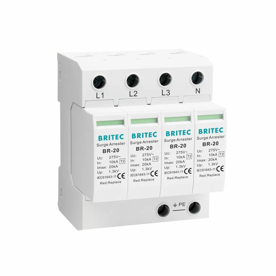
For a lower-discharge application – sub-distribution boards, machine control panels, or boards feeding sensitive electronics – a 20 kA four-pole device is often the economical choice, such as the BR-20 4P Type 2 20kA surge protective device shown below, which shares the same DIN-rail format, green/red windows, and plug-in maintenance concept.
● Ignoring a single red pole. One failed pole means that phase is unprotected while the panel looks “mostly fine.” Replace the whole set.
● No records. Without logs you cannot distinguish a device that absorbed two surges from one that absorbed two hundred – and you will replace either too early or too late.
● Skipping the backup protector check. An SPD without a functioning dedicated backup fuse or breaker cannot safely disconnect at end of life, which is how varistor failures escalate into panel incidents.
● Long, bundled connecting leads. Neat-looking but long leads add impedance that can double the effective clamping voltage at the load. Short and direct wins.
● Replacing like-for-like without re-checking the system. If loads, supply transformations, or the earthing arrangement changed since installation, re-verify the Uc rating and SPD type before reuse. Most preventable failures trace back to causes covered in our article on common SPD failure causes and solutions.
Not sure which replacement modules your boards need?
Send Britec your panel schedule or a photo of the installed SPD label. Our engineers will confirm the correct Uc variant, discharge current, and remote-signaling option – typically within one working day.
Inspect visually once a month and after every major thunderstorm. Add a full instrumented check – re-torque, thermal scan, earthing continuity, remote-signaling test – once a year, or quarterly for hospitals, data centers, and continuous-process plants. Sites with more than 25 thunderstorm days per year should tighten both intervals.
Red means the thermal disconnector inside that pole has separated the degraded MOV from the supply – the pole has reached end of life and no longer clamps surges. The module must be replaced. Best practice is to replace all four poles as a matched set, since the remaining modules have aged under the same surge history.
Technically the plug-in module swaps out individually, but you should not: mixing new and aged varistors produces unbalanced clamping levels across L1, L2, L3, and N, and the old modules are statistically close to their own end of life. Replacing the complete set costs little more and restores the manufacturer’s original protection level.
Service life depends on surge exposure, not the calendar alone. In moderate-exposure locations, three to five years is typical; at high-lightning or heavy-switching sites it can be one to two years. The status windows and your inspection log are the true lifecycle indicators – a device that diverts frequent large surges will show degradation well before an arbitrary expiry date.
Yes. Every SPD installation requires a dedicated backup protector – typically a 100 A gG fuse or equivalent breaker for a 40 kA Type 2 device – so that an end-of-life module can disconnect safely without dragging the whole board into a fault. Check this protector during every inspection: a tripped backup protector is itself a maintenance signal that the SPD has absorbed a major event.
The standard kit is a calibrated torque screwdriver, an infrared thermometer or thermal camera, a low-resistance ohmmeter for earthing continuity, and access to the BMS/SCADA alarm list for remote-signaling verification. Specialized SPD testers that measure varistor leakage current are useful on critical boards, but for most sites the combination of status windows, thermography, and disciplined records is sufficient.
● When Should You Use A 4 Pole Surge Protection Device
● How To Test An Industrial Surge Protection Device
● How Long Do Industrial Surge Protectors Last? Lifespan And Replacement Guide
● Common SPD Surge Protective Device Failure Causes And Solutions
● SPD Neutral Line Fault Analyze
● Pemasangan Perangkat Perlindungan Lonjakan Listrik AC, Commissioning