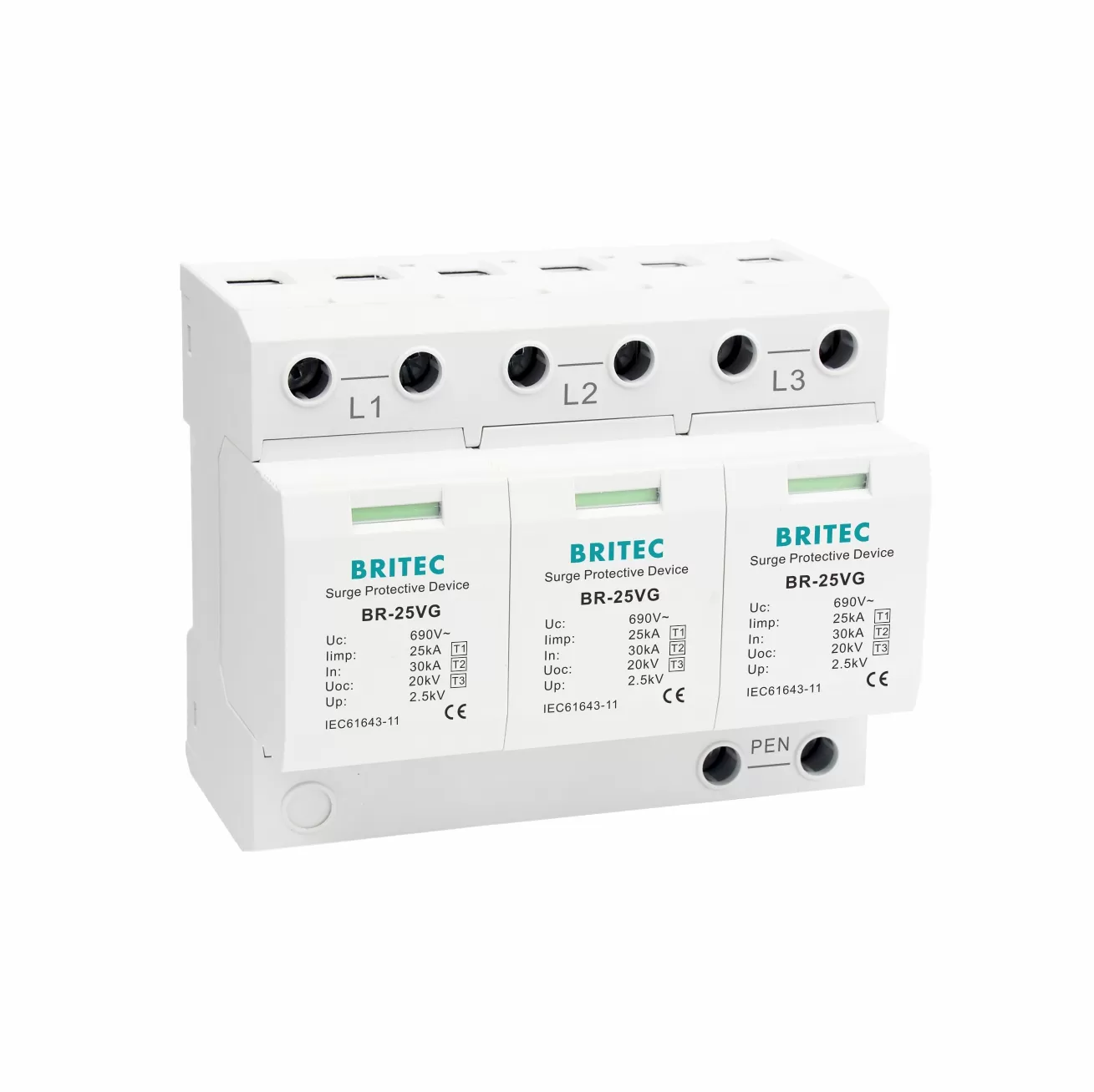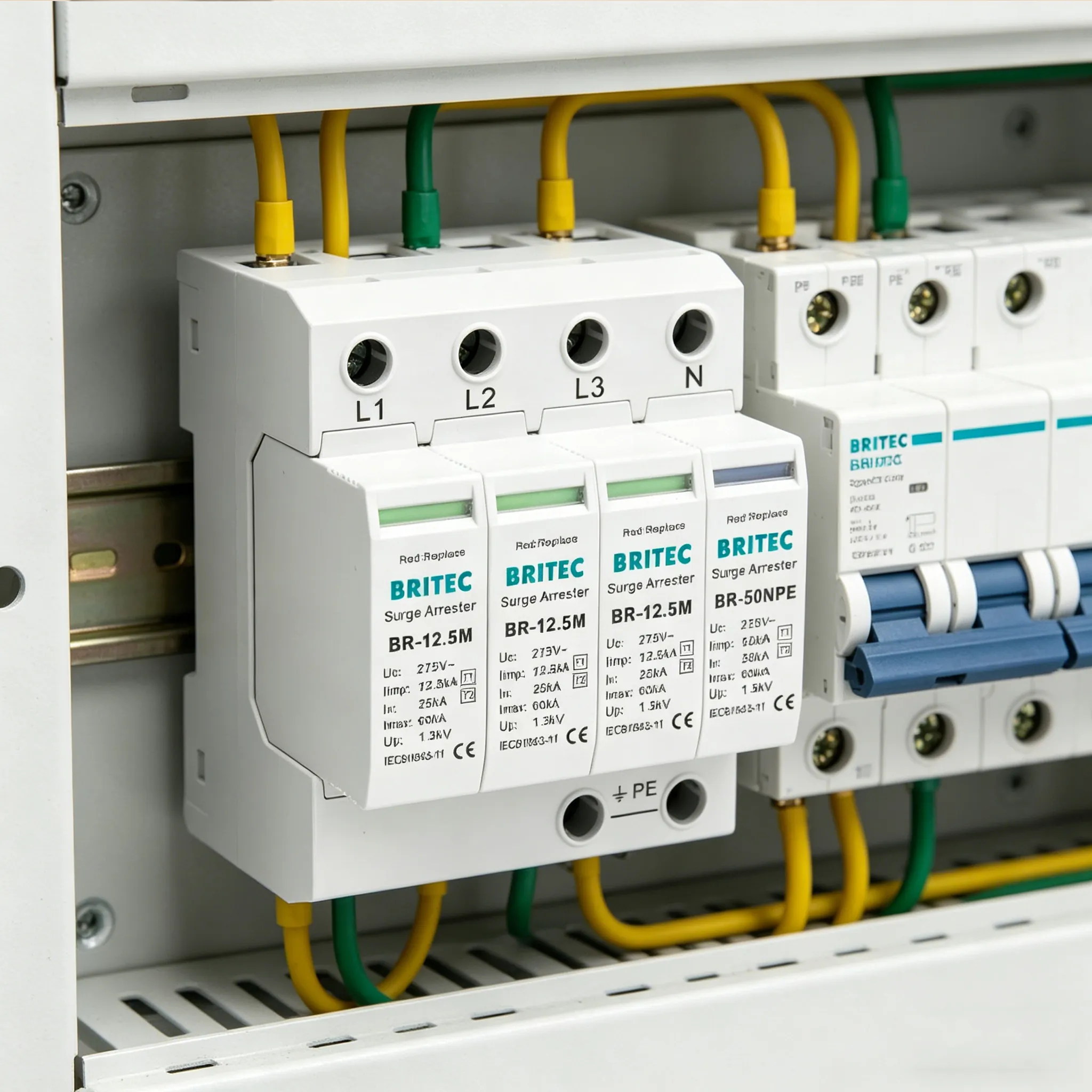

Two DC surge protective devices can carry identical figures on the datasheet and behave completely differently after three years on a solar array. The specification tells you what the device did once, in a laboratory, when it was new. What it does not tell you is which grade of zinc oxide went into the varistor block, how the thermal disconnect was assembled, or whether every unit was impulse-tested before it shipped.
Those decisions are made on the production line, and they determine service life more than any single published number. This article follows a DC SPD through the six stages of its manufacture, so you know what you are actually buying when you compare two products.
Everything begins with a sintered ceramic disc of zinc oxide doped with bismuth, cobalt and manganese oxides. The grain structure formed during sintering is what gives the varistor its non-linear behaviour: highly resistive at normal voltage, sharply conductive above the clamping threshold.
Two variables set the device’s capability. Grain uniformity determines how evenly current distributes across the disc — irregular grain boundaries create hot spots that fail early under repeated pulses. Disc diameter sets energy handling: a larger wafer absorbs more joules and runs cooler for a given surge, which is why a physically bigger module usually carries a higher Imax. In Britec’s BRPV3-1000-20, that translates to a maximum discharge current of 80kA on the 8/20 μs waveform.
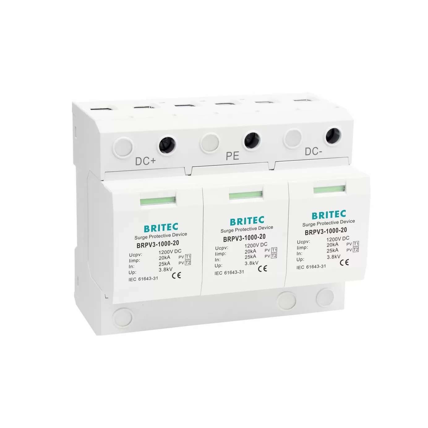
The BRPV3-1000-20 in plug-in module format — the varistor block sits inside each replaceable cartridge, with the status window reporting its condition.
This stage is where DC construction departs from AC entirely. An alternating supply crosses zero volts a hundred times a second, and any arc drawn inside a device is extinguished at that crossing. A DC bus never crosses zero. Once an arc establishes, nothing in the supply puts it out.
The answer is topology. A gas discharge tube is placed in series with the varistor so that the GDT’s own arc voltage assists extinction, and the assembly is arranged to interrupt follow current rather than sustain it. Protection modes are built accordingly — positive to earth, negative to earth, and positive to negative — so every path from the array to the inverter is covered. Getting this wrong does not produce a device that protects slightly less well; it produces one that can sustain a DC arc, which is a fire risk rather than a performance shortfall.
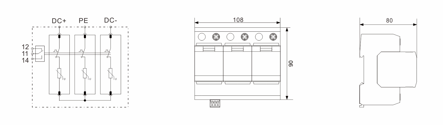
The internal topology showing protection modes (+)→PE, (−)→PE and (+)→(−) — the arrangement that allows a DC device to interrupt follow current.
Varistors do not fail open. As they age, leakage current rises, the disc heats, and heating accelerates leakage — a runaway that ends in a short circuit unless something intervenes.
That something is a thermal disconnect: a spring-loaded contact held by a solder alloy chosen to melt at a specific temperature. When the varistor overheats, the solder releases, the spring pulls the contact clear, and the device isolates itself. The assembly is unforgiving of tolerance drift. Solder alloy composition sets the trip temperature, spring force sets separation speed, and the mechanical linkage must also drive the status window from green to red so the failure is visible. A disconnect that trips late has already allowed thermal damage; one that trips early takes a working device out of service.
The housing is injection-moulded from a flame-retardant thermoplastic rated UL94 V-0 — a classification requiring the material to self-extinguish within ten seconds after flame removal, without dripping. In a component whose end-of-life failure mode involves heat, this is not a formality.
Moulding tolerances then determine two practical things: whether plug-in modules seat firmly enough for reliable contact pressure across years of thermal cycling, and whether the 35 mm DIN rail clip holds under vibration. Britec’s DC range is rated IP20 for indoor and enclosure mounting, with an operating range of −40°C to +80°C.
Terminals accept conductors from 4 mm² to 35 mm², and the plating on them is a long-term reliability decision rather than a cosmetic one. Contact surfaces oxidise; oxidation raises resistance; resistance produces heat at exactly the point where a surge needs the lowest possible impedance. Nickel or tin plating over a copper alloy base resists this.
Internal busbars carrying current from terminal to varistor block are sized for the peak the device claims, not for its continuous rating, since surge current is what actually flows through them. Assembly torque is controlled and recorded, because a connection tightened by feel is a connection that loosens under thermal cycling.
The final stage separates manufacturers from assemblers. Impulse testing on the 8/20 μs waveform verifies clamping behaviour and confirms the device performs as its datasheet claims — the BRPV3-1000-20 is rated Iimp 20kA on 10/350 μs, In 25kA and Imax 80kA on 8/20 μs, with Up ≤3.8kV and response time ≤25 ns.
Accelerated aging holds the varistor at elevated temperature and voltage to reveal units that would drift in service. Leakage current measurement at operating voltage catches wafers with grain defects, since leakage is the earliest indicator of a disc that will run hot. A manufacturer with an in-house impulse laboratory can apply these tests to production batches; one that outsources testing can only afford them at certification milestones, which means the units shipping to you two years into a contract may never have been verified at all.
The table below sets out the components inside a DC surge protective device, the material or specification used, and why each one governs how long the device lasts.
| Component | Material / Specification | Why It Determines Service Life |
|---|---|---|
| Varistor block | Sintered zinc oxide with bismuth, cobalt, manganese dopants | Grain uniformity sets current distribution; hot spots from irregular grains cause early failure |
| Varistor diameter | Sized to the target Imax (80kA on BRPV3-1000-20) | Larger discs absorb more energy per pulse and run cooler, extending life |
| Gas discharge tube | Sealed ceramic-metal envelope, series-connected | Enables DC arc extinction where no zero crossing exists |
| Thermal disconnect | Solder alloy with defined melting point plus spring contact | Trip temperature accuracy decides whether the device isolates before thermal damage |
| Housing | Thermoplastic UL94 V-0, IP20 | Self-extinguishing behaviour contains an end-of-life thermal failure |
| Terminals | Plated copper alloy, 4–35 mm² capacity | Plating resists oxidation that would raise contact resistance over time |
| Status indication | Mechanical window linked to the disconnect (green/red) | Makes silent end-of-life visible during inspection |
| Temperature rating | −40°C to +80°C operating range | Determines whether outdoor enclosure conditions accelerate ageing |
Two rows deserve particular weight when you compare products. The thermal disconnect is the only component whose job is to fail correctly, and it is invisible on a datasheet — you can judge it only through certification and manufacturer track record. And the varistor diameter is the honest indicator behind a kA claim: energy handling comes from mass, so a small module claiming a very large figure is worth questioning.
Five checkpoints run through the process. Incoming material inspection verifies zinc oxide composition and varistor electrical characteristics before assembly begins, since a defective wafer accepted here becomes a field failure two years later. In-process checks confirm thermal disconnect assembly and torque values at the point of assembly rather than after.
Electrical verification measures clamping voltage and leakage current on finished modules. Impulse verification applies test waveforms to batch samples, confirming that production units match the design that was certified. Finally, batch traceability links every finished device to its wafer lot, assembly date and test results — which is what allows a manufacturer to isolate a problem to one batch instead of recalling everything, and what lets you get a real answer if a unit is returned from site.
Britec Electric Wenzhou has manufactured surge protective devices since 2003, with ISO 9001 and ISO 14001 certification and an impulse testing laboratory on site — so production batches are verified on the 8/20 μs and 10/350 μs waveforms, not only design samples at certification. The supply chain is traceable from incoming wafer through to finished module.
The DC range covers PV Type 1+2 and PV Type 2 devices for generator voltages up to 1000V, 1200V and 1500V, plus low-voltage DC arresters, all in plug-in module format on 35 mm DIN rail with UL94 V-0 housings, green/red status windows and optional remote signalling contacts. Products conform to IEC 61643-31 and EN 61643-31, and OEM programmes are supported on roughly 45-day tooling where a project requires a non-standard configuration.
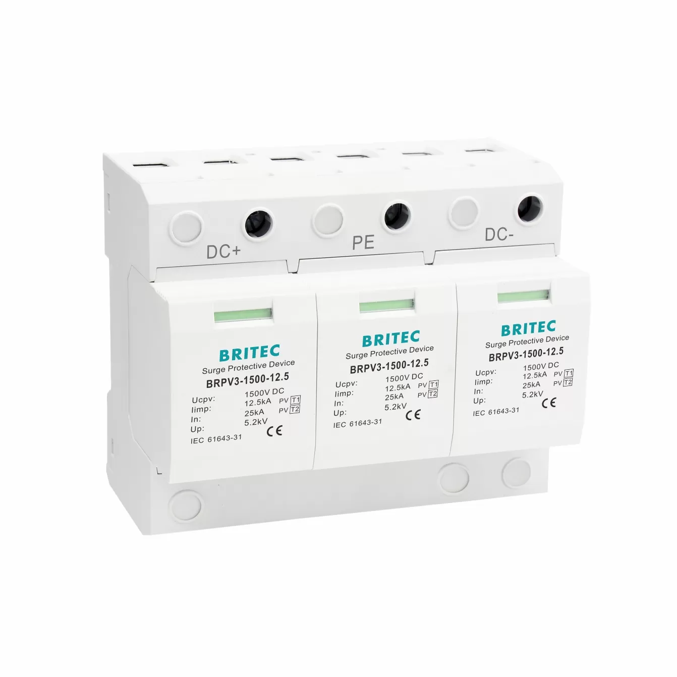
The BRPV3-1500-12.5 for 1500V generator voltages — same plug-in module construction, with the varistor mass scaled to a 60kA Imax.
The core is a metal oxide varistor block of sintered zinc oxide, usually combined with a series gas discharge tube for DC arc extinction. Around them sit a thermal disconnect mechanism, a flame-retardant UL94 V-0 housing, plated terminals and internal busbars, and a mechanical status indicator linked to the disconnect. Most designs package the active components in a replaceable plug-in module.
Because DC has no zero crossing. In an AC circuit any arc is extinguished naturally a hundred times a second, but a DC arc, once struck, continues until something interrupts it. DC devices therefore use series GDT topology and disconnect arrangements engineered to break follow current. Fitting an AC device on a DC circuit risks a sustained arc, which is a fire hazard rather than a performance compromise.
Flame-retardant thermoplastic rated UL94 V-0, which must self-extinguish within ten seconds of flame removal without dripping. This matters specifically because the end-of-life failure mode of a varistor involves heat, so the housing has to contain a thermal event rather than propagate it. Britec DC devices use UL94 V-0 housings rated IP20.
Through impulse testing on the specified waveforms to verify clamping behaviour, accelerated aging to identify units that would drift in service, and leakage current measurement to catch varistors with grain defects. Manufacturers with in-house impulse laboratories can apply these to production batches; those who outsource testing typically test only at certification stages.
Yes. Every surge absorbed causes a small permanent change in the varistor, and leakage current rises gradually as a result. This is why devices include thermal disconnects and status indication — the green-to-red window tells you the module has reached end of life. On PV installations, check the indicator during routine array inspection and replace modules rather than whole units where the design allows it.
The performance of a DC surge protective device is decided by choices you cannot see on a datasheet — the grain uniformity of the zinc oxide wafer and the diameter that sets its energy capacity, the series GDT topology that lets the device interrupt a DC arc where no zero crossing exists, the solder alloy in a thermal disconnect whose only job is to fail correctly, the UL94 V-0 housing that contains that failure, and the impulse, aging and leakage tests that either run on every production batch or only on the samples sent for certification; when you compare two products with similar published figures, these are the differences that separate a device still protecting your array in year eight from one that quietly reached end of life in year three. If you are specifying DC or PV surge protection for a project, contact Britec Electric at [email protected] tai +86 0577-6260 5321 for datasheets, test reports and a quotation on the voltage ratings your installation requires — our technical team responds to all enquiries within 24 hours.