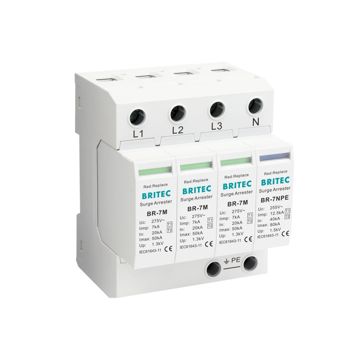
Produkteigenschaften:
| Spezifikation | BR-7M 150 3+1 | BR-7M 275 3+1 | BR-7M 320 3+1 | |
| SPD-Klassifizierung gemäß EN61643-11 | Typ 1 + Typ 2 | Typ 1 + Typ 2 | Typ 1 + Typ 2 | |
| SPD-Klassifizierung gemäß IEC61643-11 | Klasse I + Klasse II | Klasse I + Klasse II | Klasse I + Klasse II | |
| Max. Dauerbetrieb mit Wechselstrom Stromspannung | Uc(L-N/N-PE) | 150 V/255 V (50/60 Hz) | 275 V/255 V (50/60 Hz) | 320 V/255 V (50/60 Hz) |
| Blitzstoßstrom (10/350μs) | Iimp(L-N/N-PE) | 7kA/12,5kA | 7kA/12,5kA | 7kA/12,5kA |
| Nennentladestrom (8/20μs) | In(L-N/N-PE) | 20kA/40kA | 20kA/40kA | 20kA/40kA |
| Max. Entladestrom (8/20μs) | Imax(L-N/N-PE) | 50kA/80kA | 50kA/80kA | 50kA/80kA |
| Spezifische Energie | W/R(L-N/N-PE) | 12,25 kJ/Ω, 39 kJ/Ω | 12,25 kJ/Ω, 39 kJ/Ω | 12,25 kJ/Ω, 39 kJ/Ω |
| Spannungsschutzniveau | Oben (L-N/N-PE) | ≤0,8kV/≤1,5kV | ≤1,3 kV/≤1,5 kV | ≤1,5 kV/≤1,5 kV |
| Kurzschlussstromfestigkeit AC. | Isccr | 25kA rms | 25kA rms | 25kA rms |
| Max. Backup-Sicherung | 125A gG | 125A gG | 125A gG | |
| Temporäre TOV-Überspannungsfestigkeit | UT(L-N) | 180V/5Sek. | 335V/5Sek. | 400V/5Sek. |
| Vorübergehender TOV-sicherer Überspannungsfehler | UT(L-N) | 230V/120min. | 440V/120min. | 520V/120min. |
| Temporäre TOV-Überspannungsfestigkeit | UT(N-PE) | 1200V/200ms | 1200V/200ms | 1200V/200ms |
| Ansprechzeit | tA(L-N/N-PE) | ≤25ns/≤100ns | ≤25ns/≤100ns | ≤25ns/≤100ns |
| Betriebstemperaturbereich | Di | -40℃-80℃ | -40℃-80℃ | -40℃-80℃ |
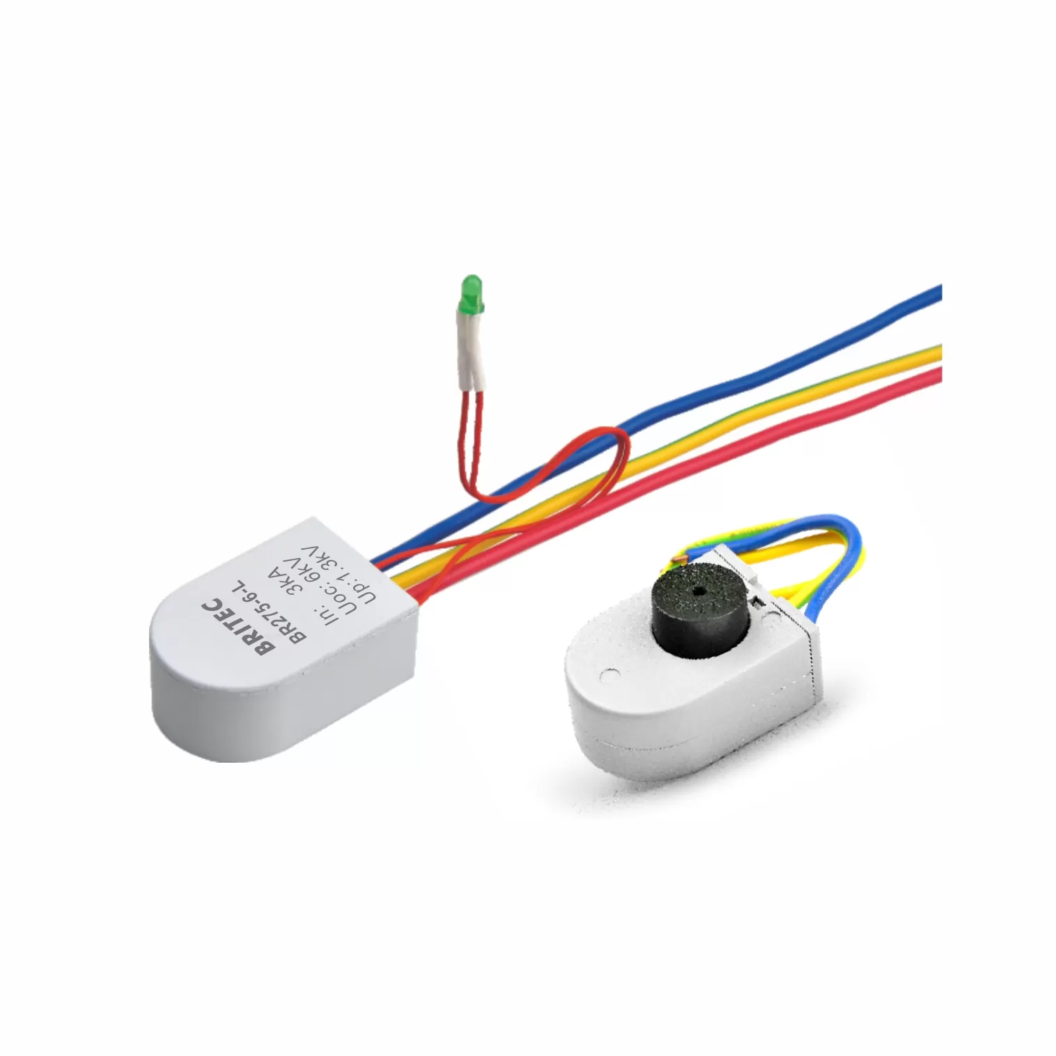
| Betriebszustands-/Fehleranzeige | grün/rot | grün/rot | grün/rot | |
| Querschnittsfläche (Min.) | 4mm² | 4mm² | 4mm² | |
| Querschnittsfläche (Max.) | 35mm² | 35mm² | 35mm² | |
| Zur Montage | 35-mm-DIN-Schiene | |||
| Gehäusematerial | Thermoplast UL94-V0 | |||
| Schutzart | IP20 | IP20 | IP20 | |
| Bestellcode | B17324 | B17326 | B17328 | |
| Bestellcode (mit Fernsignalisierung) | B17325 | B17327 | B71329 | |
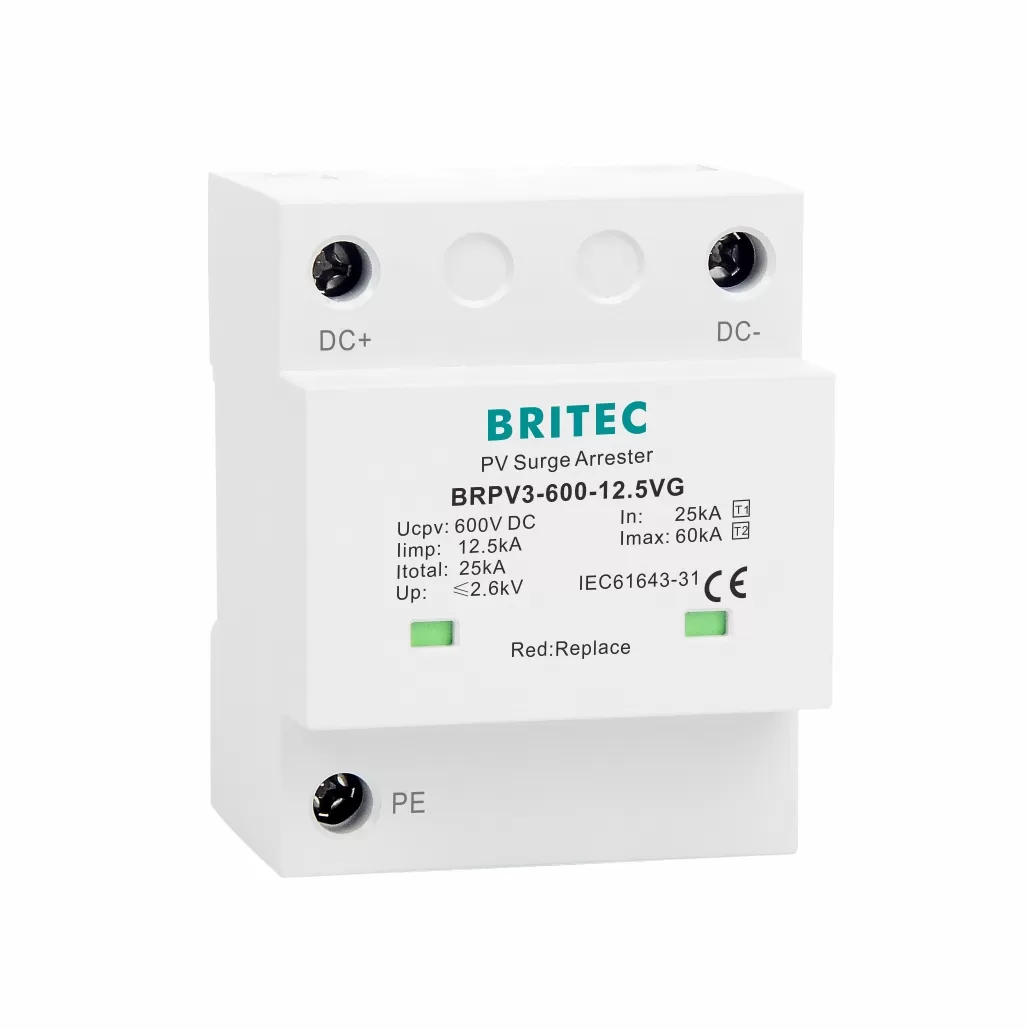
Merkmale:
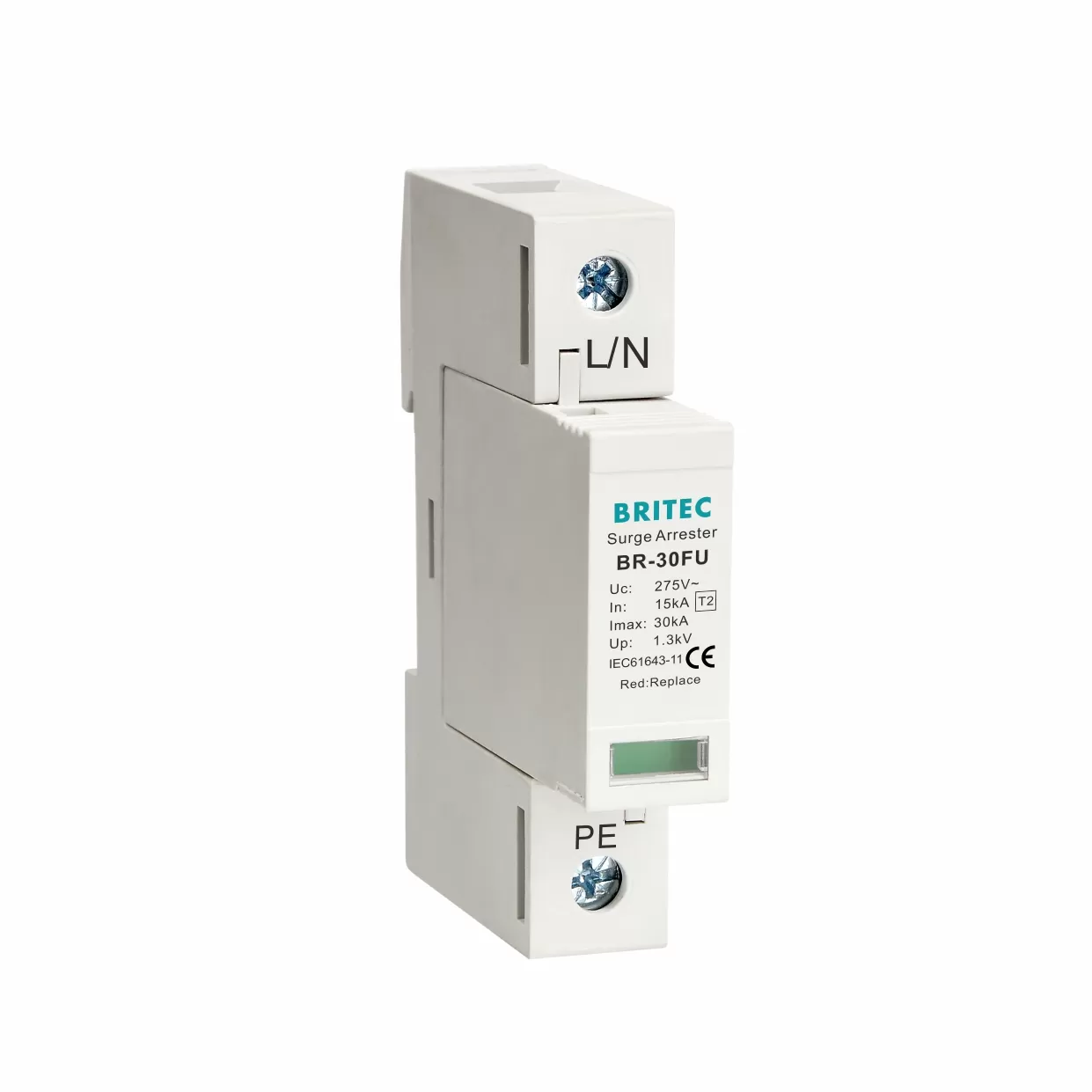
Iimp: 7kA
Visuelle Anzeige.
Präzise und einfach zu installieren.
Es handelt sich um eine Kombination aus Klasse B (10/350 us) und Klasse C (8/20 us), die am Äquipotentialanschluss der Zonen LPZ 0 und LPZ 2 verwendet wird.
Anwendung:
Es wird im Allgemeinen in der Elektroindustrie eingesetzt.
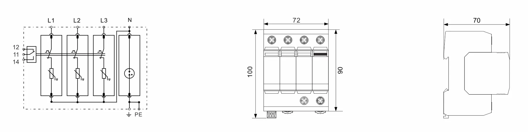
Installation:
Verkabelung entsprechend der Markierung des Überspannungsschutzes gemäß Schaltplan.
Bei der Installation gemäß dem Installationsdiagramm wird der Anschluss angezeigt, wobei l (L1, L2, L3) für die Leitung, n für Neutralleiter und PE-Erdungskabel steht, nicht verwechseln. Überprüfen Sie nach Abschluss der Installation, ob die Schutzeinheit richtig angeschlossen ist, schließen Sie den automatischen Leistungsschalter (Sicherungsschalter) und prüfen Sie, ob der Betriebsstatus normal ist.
Der Schutz, der während des Fehleranzeigefensters verwendet wird, sollte den Zustand regelmäßig überprüfen und anzeigen. Wenn das rote Fehleranzeigefenster oder das Remote-Terminal Alarmsignale ausgibt, fällt der Schutz aus und sollte rechtzeitig repariert oder ersetzt werden.
Weitere Informationen oder eine persönliche Beratung? Unsere Produkte und unser Know-how sind da, um Lösungen anzubieten.
 #!trpst#trp-gettext data-trpgettextoriginal=16#!trpen#Optimized by #!trpst#trp-gettext data-trpgettextoriginal=15#!trpen#Seraphinit-Beschleuniger#!trpst#/trp-gettext#!trpen##!trpst#/trp-gettext#!trpen#