Produkteigenschaften:
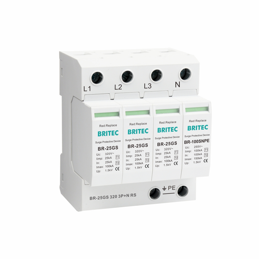
| Spezifikation | BR-25GS 150 3P+N | BR-25GS 275 3P+N | BR-25GS 320 3P+N | |
| SPD-Klassifizierung gemäß EN61643-11 | Typ 1 + Typ 2 | Typ 1 + Typ 2 | Typ 1 + Typ 2 | |
| SPD-Klassifizierung gemäß IEC61643-11 | Klasse I + Klasse II | Klasse I + Klasse II | Klasse I + Klasse II | |
| Nennbetriebs-Wechselstrom Stromspannung | Un | 120 V/240 V (50/60 Hz) | 230 V/400 V (50/60 Hz) | 240 V/415 V (50/60 Hz) |
| Max. Dauerbetrieb mit Wechselstrom Stromspannung | Uc (L-N/N-PE) | 150 V/255 V (50/60 Hz) | 275 V/255 V (50/60 Hz) | 320 V/255 V (50/60 Hz) |
| Blitzstoßstrom (10/350μs) | Iimp (L-N/N-PE) | 25kA/100kA | 25kA/100kA | 25kA/100kA |
| Nennentladestrom (8/20μs) | In (L-N/N-PE) | 25kA/100kA | 25kA/100kA | 25kA/100kA |
| Max. Entladestrom (8/20μs) | Imax (L-N/N-PE) | 100kA/150kA | 100kA/150kA | 100kA/150kA |
| Menge der elektrischen Ladung (L-N, N-PE) | Q (L-N/N-PE) | 12,5As/50As | 12,5As/50As | 12,5As/50As |
| Spezifische Energie (L-N, N-PE) | W/R (L-N/N-PE) | 156 kJ/Ω, 2500 kJ/Ω | 156 kJ/Ω, 2500 kJ/Ω | 156 kJ/Ω, 2500 kJ/Ω |
| Spannungsschutzniveau | Oben (L-N/N-PE) | ≤1,5 kV/≤1,5 kV | ≤1,5 kV/≤1,5 kV | ≤1,5 kV/≤1,5 kV |
| Max. Backup-Sicherung | 200A gG | 200A gG | 200A gG | |
| Kurzschlussstromfestigkeit AC. | Isccr | 25kA | 25kA | 25kA |
| Befolgen Sie die aktuelle Löschfähigkeit a.c. | Ifi (L-N/N-PE) | 25kA/100A | 25kA/100A | 25kA/100A |
| Temporäre TOV-Überspannungsfestigkeit | UT (L-N) | 230V/120min. | 440V/120min. | 580V/120min. |
| Temporäre TOV-Überspannungsfestigkeit | UT (N-PE) | 1200V/200ms | 1200V/200ms | 1200V/200ms |
| Ansprechzeit | tA | ≤100ns | ≤100ns | ≤100ns |
| Leckstrom | Ipe | <0,1 mA | <0,1 mA | <0,1 mA |
| Betriebstemperaturbereich | Di | -40℃-85℃ | -40℃-85℃ | -40℃-85℃ |
| Betriebszustands-/Fehleranzeige | grün/rot | grün/rot | grün/rot | |
| Querschnittsfläche (Min.) | 4mm² | 4mm² | 4mm² | |
| Querschnittsfläche (Max.) | 35mm² | 35mm² | 35mm² | |
| Zur Montage | 35-mm-DIN-Schiene | |||
| Gehäusematerial | Thermoplast UL94-V0 | |||
| Schutzart | IP20 | IP20 | IP20 | |
| Bestellcode | B17058 | B17071 | B17096 | |
| Bestellcode (mit Fernsignalisierung) | B17059 | B17072 | B17097 | |
| Suffixe: Fügen Sie das Suffix “RS” für die Version mit Trockenkontakt-Fernsignalisierung hinzu. Beispiel: BR-25GS 275 3P+N RS | ||||
Merkmale:
Typ: T1+T2 Überspannungsschutz
Reaktionszeit: ≤100 ns
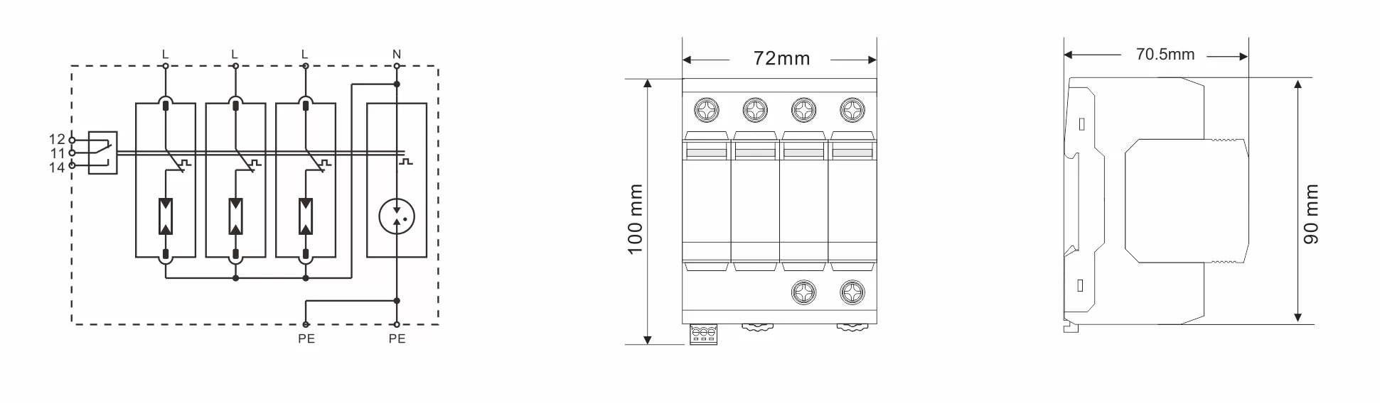
Beschriftete Anschlüsse.
Verbundtyp: 3P+N.
Montage: Standardschiene 35 mm.
Entwickelt, um elektrische Niederspannungsinstallationen vor elektrischen Überspannungen zu schützen, die durch Schaltvorgänge, Blitzeinschläge und elektromagnetische Impulse verursacht werden.
Gemäß IEC61643-11.
Thermische Trennvorrichtung.
Schraubklemmenanschluss.
Anwendung:
Schützt Elektroinstallationen vor direkten Blitzeinschlägen und leitet den Rückstrom von Blitzen ab, die sich vom Erdleiter auf die Netzleiter ausbreiten.
Das Gerät ist für den Einsatz zwischen Zone O und Zone 1 (gemäß IEC 62305-4-Definition des Blitzschutzbereichs) konzipiert.
Kann zum Schutz eines dreiphasigen Stromsystems verwendet werden.
Bei der Installation von SPD müssen folgende Dinge beachtet werden:
Bestimmen Sie den Entladestrompfad.
Markieren Sie die Leitungen, die einen zusätzlichen Spannungsabfall am Geräteanschluss verursachen.
Markieren Sie den Schutzleiter jedes Geräts, um unnötige Induktionsschleifen zu vermeiden.
Zwischen Gerät und SPD wird eine Potenzialausgleichsverbindung hergestellt.
Schließen Sie das Gerät während der Installation gemäß dem Installationsdiagramm an, wobei L die Phasenleitung, N die Neutralleitung und PE die Erdungsleitung ist. Schließen Sie das Gerät nicht falsch an.
Weitere Informationen oder eine persönliche Beratung? Unsere Produkte und unser Know-how sind da, um Lösungen anzubieten.
 #!trpst#trp-gettext data-trpgettextoriginal=16#!trpen#Optimized by #!trpst#trp-gettext data-trpgettextoriginal=15#!trpen#Seraphinit-Beschleuniger#!trpst#/trp-gettext#!trpen##!trpst#/trp-gettext#!trpen#