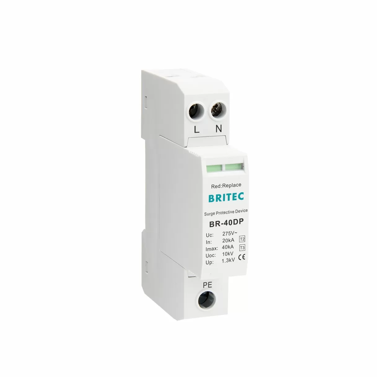
A Type 2 Surge Protection Device (Type 2 SPD) is the backbone of surge protection inside modern electrical systems. Installed at the main distribution board or control cabinet, it acts as the second shield in a layered defense strategy — catching residual surges left by upstream Type 1 SPDs and suppressing transients generated inside the network.
These devices protect against 8/20 μs impulse currents that occur from lightning-induced surges, switching events, or utility disturbances.
To ensure reliable, long-term protection, engineers and technical buyers need to understand several key aspects of a Type 2 SPD:
According to the IEC/EN 61643-11 standard, a **Type 2 SPD** is a Class II device. It is designed for locations that do not have direct lightning strikes. However, these locations still face a risk of strong transient overvoltages..
Key characteristics:
Tested with 8/20 μs current waveforms.
Typical nominal discharge current (In) is between 5–20 kA, with maximum discharge current (Imax) up to 40–80 kA.
Mounted on the load side of the electrical service panel.
Protects against both external residual surges and internal switching surges.
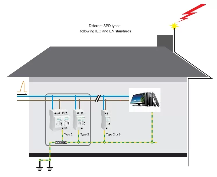
In practical application, a Type 2 SPD sits after a Type 1 device and before any downstream Type 3 point-of-use protection, forming part of a multi-stage surge protection system.
A Type 2 SPD operates on the voltage clamping principle. Under normal voltage, it remains passive. When a transient surge exceeds its maximum continuous operating voltage (Uc), its internal components switch rapidly to a conductive state, shunting excess energy to ground.
Typical components include:
MOV (Metal Oxide Varistor): The primary clamping element, absorbing surge energy and reducing voltage.
Hybrid circuits (MOV + GDT): Combine high surge capacity with improved long-term reliability.
Thermal disconnect system: Isolates the SPD at end-of-life to maintain safety.
Status indicator: Visual window or contact output to show operational condition.
Operation sequence:
Normal mode: High resistance, no impact on the circuit.
Surge event: Voltage rises above the Uc threshold.
Clamping: SPD diverts surge current to ground, lowering the voltage to a safe Up (voltage protection level).
Recovery: SPD returns to high-resistance standby state.
The primary role of a surge protection device Type 2 is to limit transient overvoltages to a level that downstream equipment can withstand without damage.
Key functions:
Residual surge limitation — reduces voltage after a Type 1 SPD has absorbed the bulk of the energy.
Switching surge suppression — mitigates transients from motor starts, pump switching, or other inductive load operations.
Equipment protection — prevents damage to sensitive electronics, PLCs, automation systems, and control gear.
System reliability — reduces downtime from surge-related failures.
Part of a cascade — sits between the service entrance protection (Type 1) and point-of-use devices (Type 3).
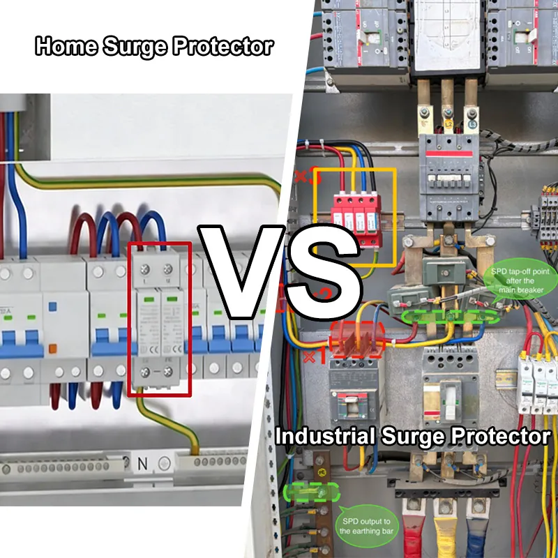
Type 2 SPDs are installed in:
Industrial facilities with lightning protection systems.
Commercial buildings to protect HVAC, elevators, lighting, and IT systems.
Machine control cabinets for industrial automation.
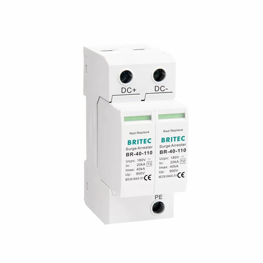
Renewable energy systems—such as solar PV inverters and wind turbine controls—require robust surge protection (see our Solar Surge Protection Devices Selection Guide and Surge Protection for Solar Photovoltaic Systems).
Hospitals and data centers where uptime is critical.
Residential main panels for whole-house protection.
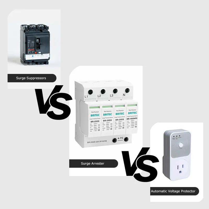
Surge protection devices have three main types. Each type has a different job in the electrical system. You can read more in our detailed guide here: Difference Between Type 1, Type 2, and Type 3 Surge Protective Devices.
| Feature | Type 1 SPD | Type 2 SPD | Type 3 SPD |
| Location | Installed at the service entrance. | Installed at the main distribution board. | Installed close to sensitive loads. |
| Test waveform | Tested with 10/350 μs lightning impulse. | Tested with 8/20 μs surge current. | Tested with 1.2/50 μs voltage + 8/20 μs current. |
| Purpose | Discharges direct lightning current. | Limits residual surges and switching surges. | Gives final protection for electronics. |
| Typical Up | ≤ 4 kV. | ≤ 2.5 kV. | ≤ 1.5 kV. |
| Examples | Buildings with a lightning protection system (LPS). | Control panels and sub-distribution boards. | IT equipment and home electronics. |
Summary:
Type 1 SPD stops most of the high-energy surge from lightning.
Type 2 SPD is the middle line of defense. It reduces remaining surge voltage and controls switching surges.
Type 3 SPD is the last step. It protects sensitive electronics from small, fast surges.
When choosing the best Type 2 surge protection device, selection should be based on system compatibility, surge risk level, and equipment sensitivity.
1. Match system voltage and earthing arrangement
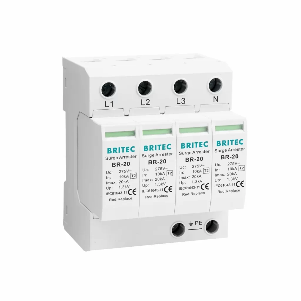
Different systems — TT, TN-S, TN-C, IT — require different SPD configurations:
4P (all-pole protection) for TN systems.
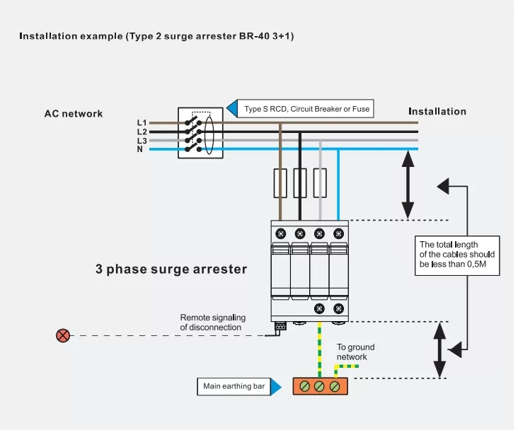
3+1 configuration (L-N protection plus N-PE module) for TT systems to handle N-PE overvoltage events.
2. Determine Uc (Maximum Continuous Operating Voltage)
Uc should be slightly above the nominal system voltage to prevent unnecessary triggering but low enough for effective protection.
3. Check discharge current capability
Nominal discharge current (In): 5–20 kA.
Maximum discharge current (Imax): 20–80 kA depending on risk level.
4. Voltage protection level (Up)
Lower Up means better protection — aim for ≤ 2.5 kV for general equipment, ≤ 1.5 kV for sensitive electronics.
5. Temporary overvoltage (TOV) withstand
Ensure the SPD can survive temporary overvoltage conditions from faults or switching events.
6. Additional features
Pluggable modules for quick maintenance.
Remote alarm contacts for monitoring.
Thermal disconnect and visual indicators.
Installation best practices from field engineering experience:
Location — Mount as close as possible to the main distribution board busbars or the equipment you want to protect.
Parallel connection — Type 2 SPDs are usually connected in parallel to the power supply.
Lead length — Keep the combined length of phase, neutral, and ground conductors under 0.5 m to avoid raising the protection voltage.
Conductor cross-section — At least 6 mm² copper for Type 2; larger sizes for higher-capacity devices.
Earthing — Connect directly to the main equipotential bonding bar with the shortest path.
Overcurrent protection — Use fuses or circuit breakers sized according to the SPD’s maximum short-circuit withstand.
Coordination in cascaded systems — If installed downstream of a Type 1 SPD, maintain a separation distance (>10 m) or install a decoupling inductor to ensure proper energy sharing.
System-specific wiring — For TT systems, include an N-PE protection module to handle neutral-to-earth surges.
Following these guidelines ensures the SPD performs to specification and complies with electrical standards.
A Type 2 Surge Protection Device is a vital element in layered electrical protection. It safeguards against residual surges from lightning and internal switching events, ensuring equipment longevity and operational stability.
By understanding its working principle, installation rules, and selection parameters, engineers and procurement managers can specify devices that meet system requirements, comply with IEC/EN 61643-11, and deliver reliable protection for years to come.
Correctly installed, a Type 2 SPD is not just a component — it’s an insurance policy for your electrical system. Learn more about solar SPD applications and how to choose the right one.
 Optimized by Seraphinite Accelerator