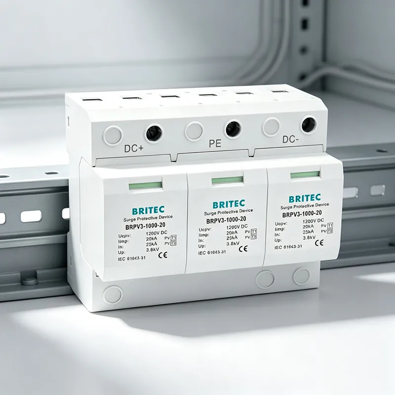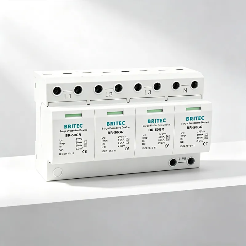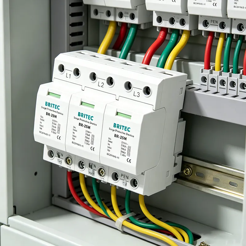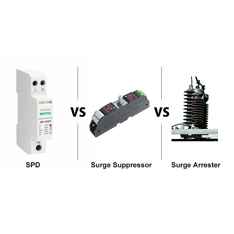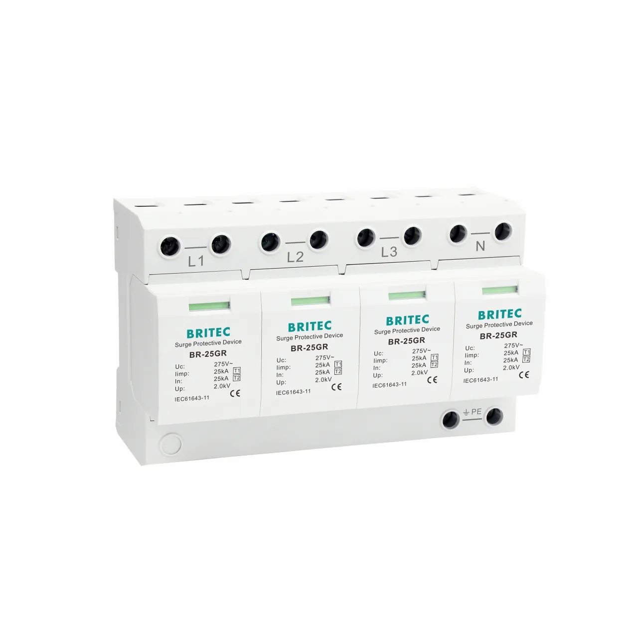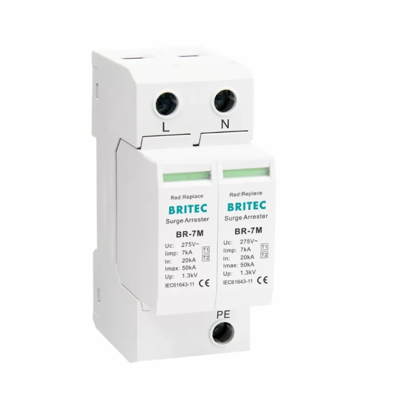

Britec Electric has manufactured surge protective devices (SPDs) since 2003, and one question comes up in almost every panel-design review: how do you combine a ประเภทที่ 1 SPD, a ประเภทที่ 2 SPD, and a ประเภทที่ 3 SPD so they protect each other instead of fighting each other? This guide explains surge protection coordination in plain engineering terms and gives you a repeatable cascade method you can apply to low-voltage systems.
Surge protection coordination is the practice of arranging SPDs in layers so that each device handles the surge energy it was built for, and no single device is asked to do the whole job. A direct lightning strike on the service entrance needs a heavy-duty Type 1 surge arrester, while the sensitive PLC next to a socket needs a low-let-through ประเภทที่ 3 SPD. Coordination makes sure the big device takes the hit first and the small device only cleans up what is left.
Before cascading, it helps to recall what each type is built for. The table below maps the type to its position in the installation.
| SPD Type | Where It Sits | What It Handles |
|---|---|---|
| ประเภทที่ 1 | Service entrance / main inbound | Direct lightning current, 10/350 µs |
| ประเภทที่ 2 | Distribution boards | Induced and switching surges, 8/20 µs |
| ประเภทที่ 3 | Point of use, near equipment | Residual overvoltage cleanup |
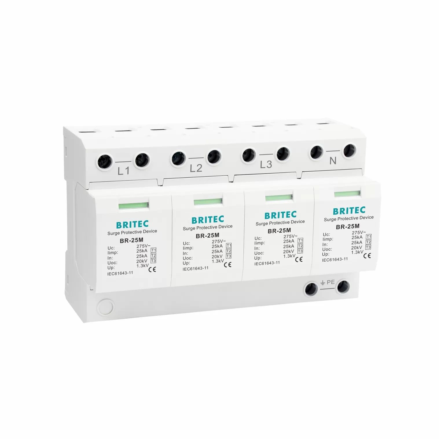
● ประเภทที่ 1 — fitted at the incoming service entrance to drain a direct lightning strike.
● ประเภทที่ 2 — fitted at distribution boards to limit surges as they spread through the building.
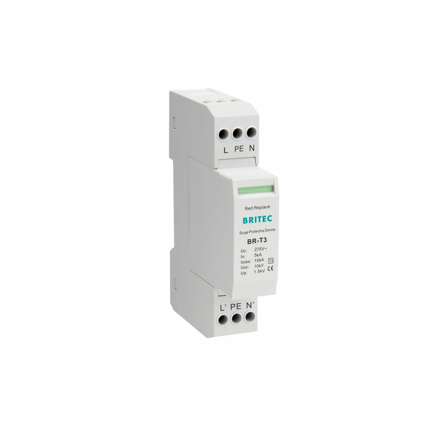
● ประเภทที่ 3 — fitted at the equipment to cut the last residual overvoltage the load sees.
Cascading is not optional on exposed or lightning-prone sites. A single Type 2 device at the main board cannot survive a direct strike, and a Type 1 alone leaves too much residual voltage for sensitive loads. The cascade closes both gaps: Type 1 drains the lightning current, Type 2 limits propagation through the board, and Type 3 finishes the job at the socket. The result is a lower voltage protection level (Up) at the equipment than any single stage could deliver. See our guide on when a Type 1 SPD is required for site-risk triggers.
Follow this sequence when you lay out a coordinated protection scheme:
● Start at the origin — fit a Type 1 (or Type 1+2) SPD at the incoming service entrance, as close to the main switch as the wiring allows.
● Add Type 2 at each distribution board — every sub-board that feeds sensitive areas gets its own Type 2 SPD so surges are limited as they spread.
● Finish at the equipment — mount a Type 3 SPD within 10 m of the load, ideally at the socket or DIN position next to it.
● Keep the decoupling distance — leave roughly 10 m of wiring between stages, or insert a coordination inductor when space is tight so the stages do not trip each other.
● Coordinate the backup protection — pair each SPD with the correct fuse or circuit breaker so a shorted SPD is isolated without dropping the feeder (see SPD and circuit breaker coordination).
Need A Coordinated SPD Layout For Your Project?
Send Britec your single-line diagram and we will return a Type 1+2+3 cascade proposal with backup protection sized to IEC 61643.
SPDs must share the surge current, not compete for it. IEC 61643-12 defines energy coordination by the discharge capacity (Iimp for Type 1, In or Imax for Type 2 and Type 3) and the wiring impedance between stages. When the physical distance is below the decoupling rule, a coordination inductor adds the impedance artificially, letting the Type 1 fire first and the Type 3 stay dormant until needed. Skipping this step is the most common cause of nuisance tripping we see in the field.
Every SPD needs a backup device that clears a follow current but does not open on a normal surge. Britec supplies dedicated backup protectors and combined SPD plus MCB units, and our Type 1 design considerations article covers sizing in detail. The backup must be coordinated with the SPD’s short-circuit rating so the feeder stays live after a fault.
A coordinated scheme is only as good as the standard behind it. Design to IEC 61643-11 for SPD construction, IEC 61643-12 for selection and application, and IEC 62305 for the overall lightning-protection system. Specifying to these standards also keeps your project auditable for insurers and regulators. Our surge protector ratings guide explains which numbers to quote in a tender.
● One SPD for the whole building — a single device cannot cover both a direct strike and point-of-use let-through.
● Ignoring the decoupling gap — stacking Type 1 and Type 3 with no distance or inductor causes both to trip.
● Wrong backup rating — an oversized fuse lets a failed SPD burn; an undersized one drops the feeder on every storm.
● Mixing brands without coordination data — only cascade devices whose manufacturer publishes coordination tables.
Britec Electric is a Wenzhou-based SPD manufacturer established in 2003, certified by Intertek SEMKO, TUV, and CE, and supplying Type 1, Type 1+2, Type 2, and Type 3 devices plus coordination inductors and backup protectors from one catalogue. That single-source coordination data is what lets your cascade actually work on paper and in the field. Explore the full Type 1, Type 2, and Type 3 ranges, or read how SPDs clamp transient overvoltage before you specify.
Talk To A Britec SPD Engineer
Get a coordinated Type 1+2+3 SPD schedule, coordination inductor sizing, and backup-protector selection for your next project.
1. What is surge protection coordination?
It is the layered arrangement of SPDs so each stage handles the surge energy it is rated for, preventing one device from being overloaded while the others stay idle.
2. Can I install a Type 1, Type 2, and Type 3 SPD together?
Yes. That is the standard cascade for exposed sites: Type 1 at the entrance, Type 2 at sub-boards, and Type 3 at the equipment, with correct decoupling between them.
3. What is the decoupling distance between SPD stages?
IEC 61643-12 typically calls for about 10 m of wiring between stages so the upstream device acts first. Where space is tight, a coordination inductor replaces that distance.
4. Do I need a Type 1 SPD if I already have a Type 2?
On lightning-prone or directly struck sites, yes. A Type 2 cannot survive the 10/350 µs lightning current that a Type 1 is built to drain.
5. What does a coordination inductor do?
It adds artificial impedance between SPD stages so they trip in the right order when physical wiring distance is too short, avoiding nuisance operation.
6. How do I coordinate an SPD with its backup fuse?
Size the backup (fuse or MCB) so it clears a failed SPD under short circuit but does not open during a normal surge, matching the SPD’s discharge and short-circuit ratings.
7. Which standard covers SPD coordination?
Coordination and application are covered by IEC 61643-12, with construction in IEC 61643-11 and the wider lightning system in IEC 62305.
8. Can I mix SPD brands in one cascade?
Only if both manufacturers publish coordination data for the combination. Otherwise the stages may not share current correctly and could trip together.
9. Where should a Type 3 SPD be installed?
As close as possible to the protected equipment, ideally within 10 m and at the final socket or DIN position feeding the load.
10. How do I know my cascade is sized correctly?
Check Iimp for Type 1, In or Imax for Type 2 and 3, the voltage protection level Up against your equipment’s withstand, and the backup rating against the prospective short-circuit current.
● Type 1 vs Type 1+2 vs Type 2 vs Type 3 SPD — Which to Choose
● What Is a Type 1 SPD and When Is It Required?
● SPD Type 1 Design Considerations For Electrical Engineers
● AC SPD Single Phase Coordination with Circuit Breakers
● How SPD Surge Protective Devices Handle Transient Overvoltage