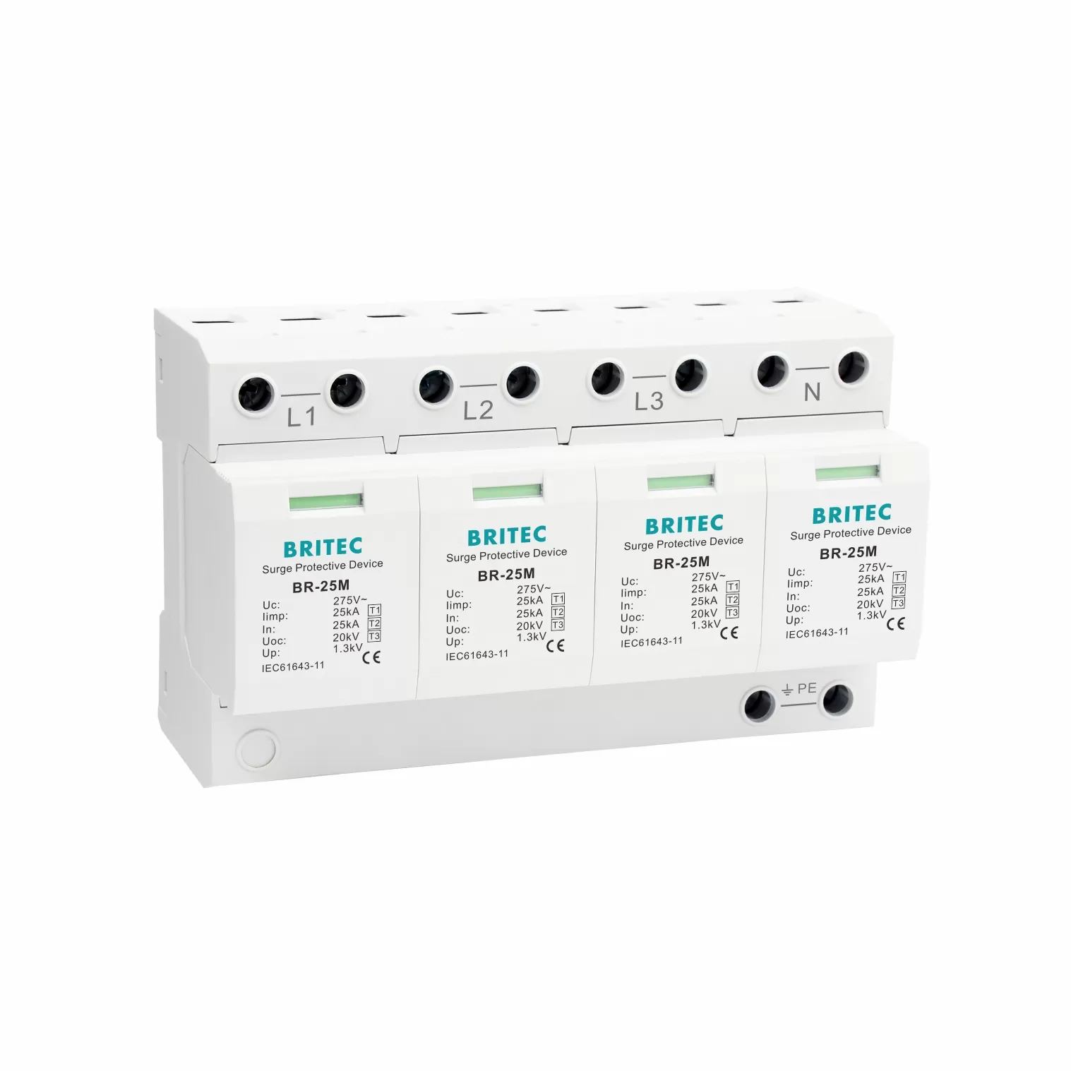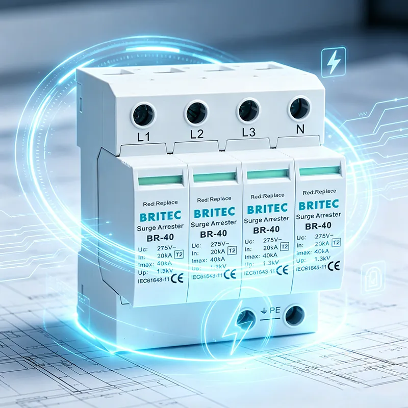

A Type 3 surge protection device (SPD) is a sacrificial component. Every time it absorbs a transient overvoltage, its internal metal oxide varistor (MOV) sustains microscopic damage that accumulates irreversibly. When the cumulative damage reaches a critical threshold, the SPD reaches end of life and can no longer protect your equipment. Understanding this process, recognising the warning signs, and knowing what happens when protection is lost are essential for any facility manager, electrical engineer, or system integrator responsible for sensitive electronic equipment. This guide explains the MOV degradation mechanism, the safe end-of-life sequence mandated by МЭК 61643-11, the consequences of operating without protection, and the maintenance practices that prevent costly equipment failure. For a broader overview of SPD classification and function, see our surge protection device overview.
Don’t Let Your Equipment Go Unprotected
When a Type 3 SPD reaches end of life, your sensitive equipment is fully exposed to transient overvoltages. Britec Electric manufactures IEC 61643-11 certified Type 3 SPDs with integrated thermal disconnection, visual status indication, and optional remote signalling. Replace failed modules quickly with pluggable designs that require no rewiring.
The core protection element inside a Type 3 SPD is the metal oxide varistor (MOV), a polycrystalline ceramic composed primarily of zinc oxide grains. At normal operating voltage, the MOV presents a very high impedance, effectively invisible to the circuit. When a transient overvoltage exceeds the varistor breakdown voltage, the MOV’s impedance drops dramatically, diverting the surge current to earth and clamping the voltage to a safe level. This clamping action protects downstream equipment from voltage spikes that would otherwise damage sensitive semiconductors, capacitors, and insulation.
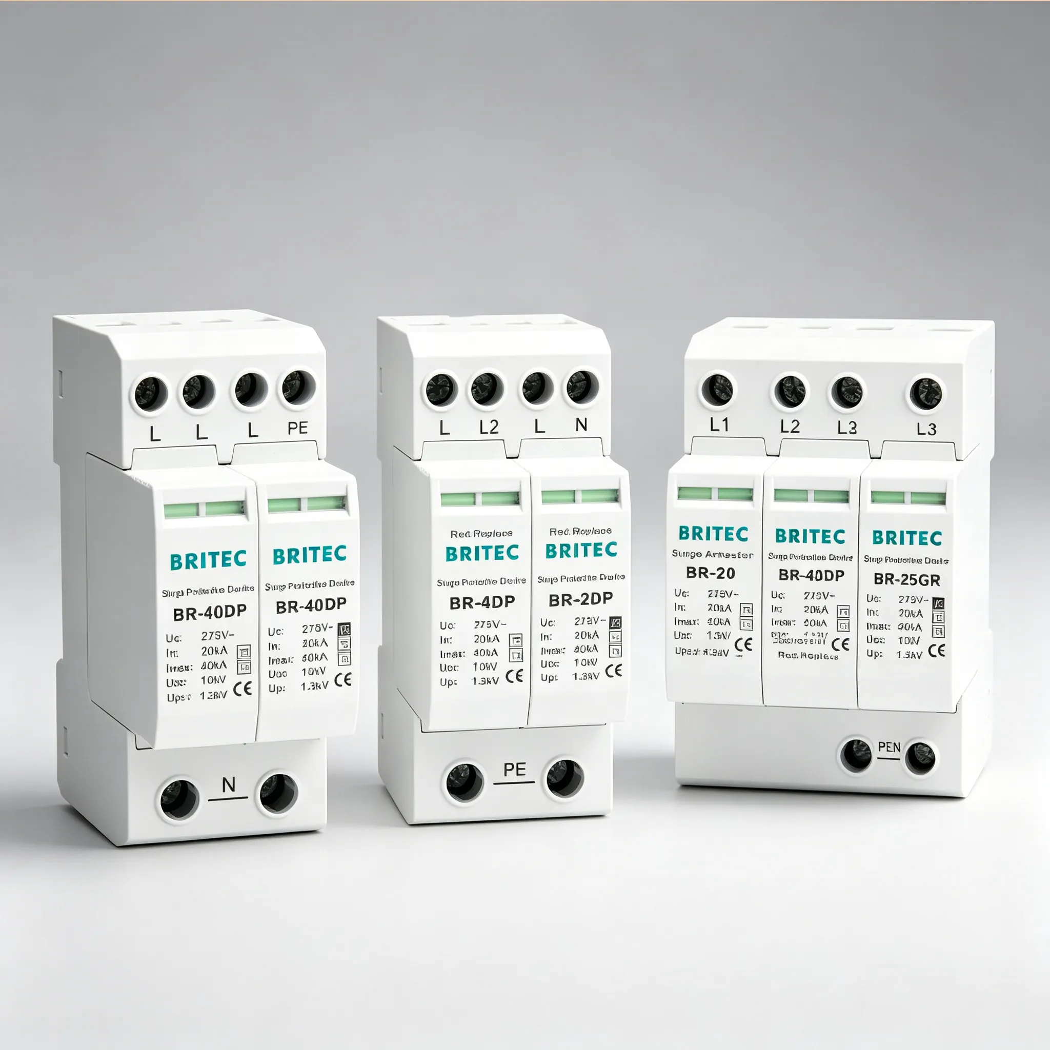
However, this protective action is not free. Each surge event forces current through the zinc oxide grain boundaries, causing microscopic structural damage at the junctions. This damage is cumulative and irreversible. The MOV does not heal between events. With each surge, the breakdown voltage gradually shifts downward and the leakage current at normal operating voltage increases. This is not a defect but the fundamental physics of metal oxide ceramics under repeated electrical stress. The BR-20DP Type 3 surge protector uses high-performance MOVs engineered for maximum surge endurance, but even the best varistors have finite service lives.
IEC 61643-11 mandates that SPDs must fail safely. The standard requires that when the MOV reaches the end of its useful life, the SPD must either continue operating within specification or disconnect itself without creating a fire hazard, sustained arcing, or a short-circuit fault that the backup protection cannot clear. This safe end-of-life sequence follows a defined chain of events:
As the MOV accumulates surge damage, its leakage current at normal operating voltage gradually increases. A new MOV typically exhibits leakage current below 0.1mA. As degradation progresses, leakage current rises into the 0.1 to 0.5mA range, indicating normal aging. Once leakage current exceeds 1mA, the MOV has significantly degraded and replacement is recommended. At this stage, the status indicator still shows green because the thermal disconnector has not yet activated. The SPD continues to provide some level of surge protection, but its clamping voltage has shifted and its surge current capacity has diminished.
Rising leakage current generates increasing heat within the MOV. At some point, the heat generated by leakage current exceeds the MOV’s ability to dissipate it, creating a positive feedback loop: higher temperature increases leakage current, which generates more heat, which raises temperature further. This is thermal runaway. The MOV temperature climbs rapidly, approaching the decomposition temperature of the zinc oxide ceramic. Without intervention, the varistor would crack, shatter, or ignite.
The thermal disconnector, a spring-loaded contact mechanically linked to the MOV housing, is calibrated to open at a specific temperature below the ignition point. When the MOV reaches this temperature, the disconnector snaps open, permanently isolating the varistor from the circuit. This is the critical safety event that constitutes the SPD’s safe end of life. The MOV is electrically dead but physically safe. The BR-T3 Type 3 surge protector incorporates this thermal disconnection mechanism as a standard feature, with a response time calibrated to activate before any fire risk develops.
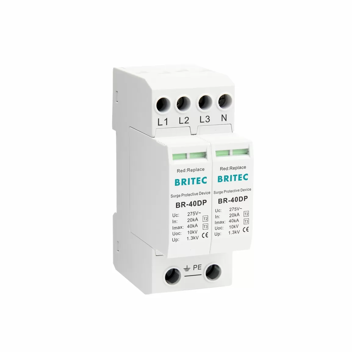
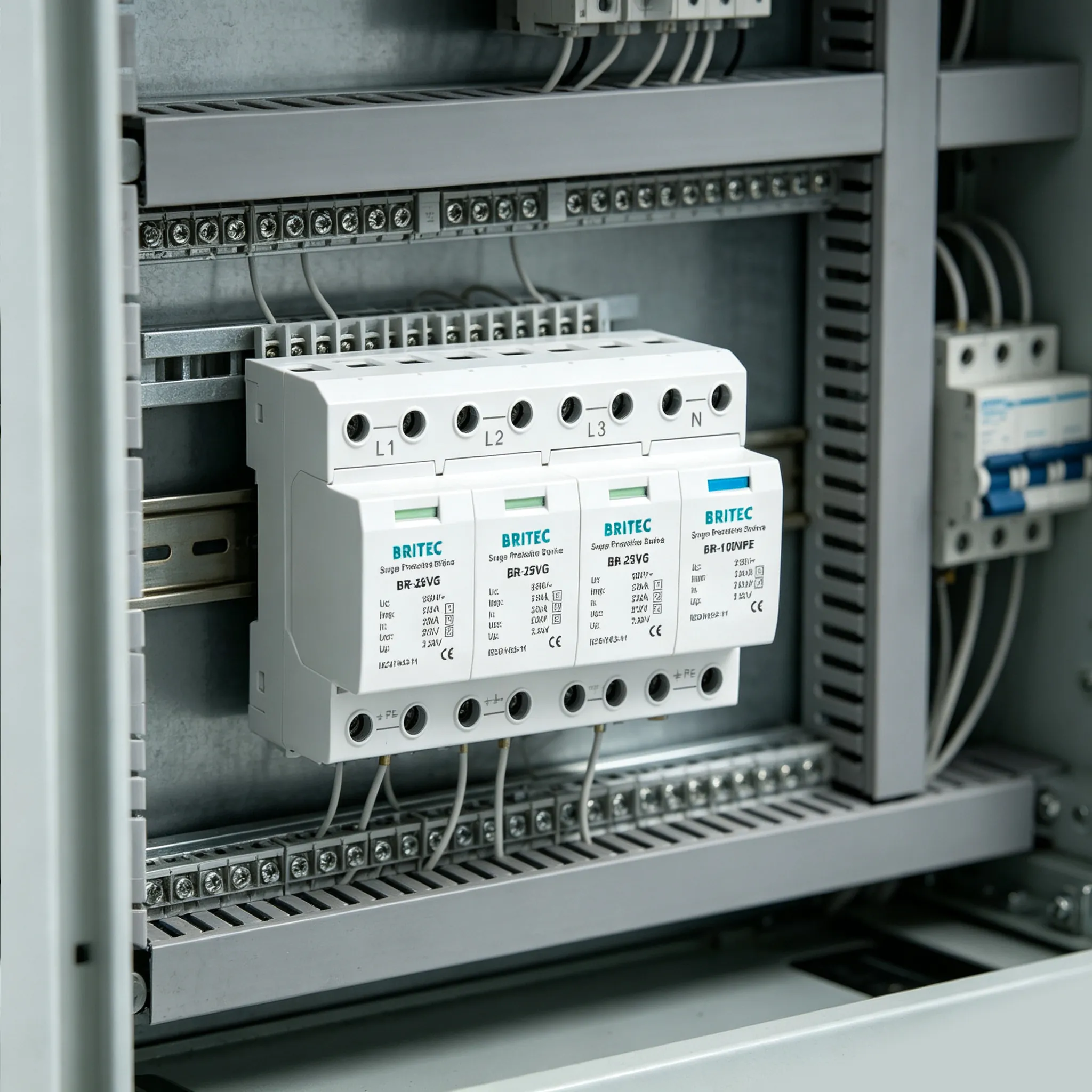
The mechanical action of the thermal disconnector simultaneously triggers the status indicator. A mechanical flag, integrated with the disconnector mechanism, changes colour from green to red, providing immediate visual confirmation that the module has reached end of life. For facilities with many SPDs installed across multiple panels, the optional remote signalling contacts change electrical state when the disconnector activates, enabling integration with a building management system (BMS) or SCADA system for automated monitoring. The BRVSPI surge protection panel status indicator provides centralised visual monitoring of multiple SPD modules on a single panel.
When the thermal disconnector activates, the power path to the load remains uninterrupted. Connected equipment continues to operate normally. This is by design: the SPD is installed in parallel with the load, and the disconnector only breaks the MOV branch, not the supply circuit. However, surge protection is now zero. Every transient overvoltage that the SPD would have clamped will now pass directly to the protected equipment. The consequences depend on the installation’s surge environment and the sensitivity of the downstream load.
| Surge Source | Typical Voltage at Equipment | Consequence Without Type 3 SPD |
|---|---|---|
| Residual from upstream Type 2 SPD | 1.0 to 1.5 kV | Damage to power supplies, PLC input cards, communication interfaces |
| Switching surge from nearby motor start | 0.8 to 2.0 kV | Gradual degradation of semiconductors, intermittent equipment faults |
| Reflected wave overshoot on cable | 1.5 to 2.5 kV | Immediate failure of low-voltage electronics, server power supplies |
| Indirect lightning induced surge | 2.0 to 4.0 kV | Catastrophic failure of all connected equipment on the circuit |
| Temporary overvoltage (TOV) | 300 to 400 V sustained | Thermal damage to equipment power supplies, capacitor rupture |
The most insidious consequence is the false sense of security. Because the equipment continues to operate, facility staff may assume the SPD is still functioning. The status indicator is often located inside an electrical panel that is rarely opened. Equipment may run for months without a surge event, reinforcing the assumption that everything is fine. Then a single switching transient or distant lightning strike destroys thousands of dollars worth of equipment that was supposed to be protected.
The safe end-of-life sequence described above depends on the thermal disconnector activating before the MOV reaches dangerous temperatures. Under certain conditions, the MOV can degrade faster than the disconnector can respond, leading to catastrophic failure instead of safe disconnection. The three primary causes are:
If a surge event delivers current exceeding the SPD’s maximum discharge current (Imax), the MOV can fail instantaneously in a low-impedance short-circuit mode before the thermal disconnector has time to react. This is why correct SPD sizing for the expected surge environment is critical. A Type 3 SPD with Imax of 20kA, such as the BR-20DP, is designed for point-of-use protection where upstream Type 1 and Type 2 SPDs have already absorbed the bulk surge energy. Installing a Type 3 SPD without upstream protection in a high-surge environment virtually guarantees premature catastrophic failure.
Temporary overvoltage forces the MOV into continuous conduction at power frequency, generating sustained heat that can overwhelm the thermal disconnector. The most common TOV cause is neutral conductor disconnection in TT and TN-C-S systems, which can raise the phase-to-earth voltage to 1.45 times the nominal voltage (approximately 335V on a 230V system) for seconds or even minutes. IEC 61643-11 tests TOV survival by applying UT (rated temporary overvoltage) for 5 seconds. An SPD with Uc too close to the system nominal voltage has insufficient TOV margin and is more likely to fail catastrophically. Selecting an SPD with Uc at least 20% above the nominal system voltage provides necessary TOV headroom.
Ambient temperatures exceeding the SPD’s rated operating range (typically -40 to +80 degrees Celsius) accelerate MOV aging and reduce the thermal disconnector’s response margin. High humidity and corrosive atmospheres, such as coastal installations or chemical plants, can degrade internal connections and housing integrity. Dust accumulation reduces heat dissipation, raising the MOV’s steady-state temperature. These factors compound over years of service, narrowing the margin between normal aging and catastrophic failure.
Diagnosing SPD end of life requires a combination of visual inspection, electrical measurement, and contextual assessment. The following methods are ranked by diagnostic reliability, from the simplest field check to laboratory-grade testing.
| Method | What It Detects | Reliability | Who Can Perform |
|---|---|---|---|
| Visual indicator check (green/red) | Thermal disconnection has occurred | High (confirmatory only) | Any trained personnel |
| Remote signalling contact | Disconnector state change | High (automated) | BMS/SCADA system |
| Housing visual inspection | Physical damage, burn marks, deformation | Середина | Maintenance technician |
| Leakage current measurement | MOV degradation before disconnection | Very High (predictive) | Qualified electrician only |
| Thermal imaging | Abnormal heating indicating partial short | Medium-High | Thermographer |
| Surge generator test (lab) | Clamping voltage and residual capacity | Definitive | Manufacturer or accredited lab |
Leakage current measurement is the most predictive diagnostic method because it detects MOV degradation before the thermal disconnector activates. A qualified electrician clamps a true RMS leakage current meter around the SPD’s PE conductor with the system energised. Readings below 0.1mA indicate a healthy MOV. Readings between 0.1 and 0.5mA indicate normal aging. Readings above 1mA are a clear warning that replacement is needed. Readings above 5mA indicate imminent failure risk. This test must be performed with appropriate personal protective equipment and only by qualified personnel, as it involves working on energised equipment.
When a Type 3 SPD reaches end of life, prompt replacement restores surge protection and eliminates the fire risk associated with a degraded module. The following practices ensure safe and efficient replacement:
1. Use identical or equivalent modules. The replacement module must match the original SPD’s electrical specifications, including Uc, In, Imax, Up, and configuration (pole count). Using a module with different characteristics can compromise cascade coordination with upstream Type 1 and Type 2 SPDs. The Britec BR-20DP and BR-T3 series use pluggable modular designs that allow module replacement without disconnecting or rewiring the base, minimising downtime.
2. Inspect the backup protection. Before installing the replacement module, verify that the upstream SCPD (fuse or MCB) is intact and correctly rated. If the SCPD tripped during the SPD’s end-of-life event, investigate whether the disconnector operated before or after the SCPD cleared the fault. Frequent SCPD tripping alongside SPD end-of-life may indicate a systemic issue such as repeated TOV events or inadequate upstream surge protection. For installations using dedicated SPD backup protectors, verify coordination per AC SPD coordination with circuit breakers.
3. Check terminal tightness and condition. Loose terminals generate heat under surge current, accelerating MOV degradation and potentially causing terminal burn damage. During replacement, verify that all connections are torqued to the manufacturer’s specification. Inspect terminals for oxidation, pitting, or heat discoloration. Replace the entire SPD base if terminal damage is evident.
4. Document the replacement. Record the date, location, SPD model, serial number, and observed failure mode (red indicator, physical damage, leakage current reading). This maintenance log supports budget planning for future replacements, demonstrates due diligence for insurance and compliance purposes, and helps identify patterns such as consistently short SPD life in specific locations that may indicate a localised surge environment problem.
5. Keep spare modules in stock. For facilities with multiple SPD installations, maintaining a small inventory of replacement modules reduces downtime from weeks to minutes. This is particularly important for critical installations such as data centres, manufacturing control systems, and medical facilities where unprotected operation carries unacceptable risk.
| Mistake | Consequence | Correct Practice |
|---|---|---|
| Installing Type 3 SPD without upstream Type 1/2 protection | Type 3 absorbs bulk surge energy it was not designed for, causing rapid or catastrophic failure | Follow IEC 61643-12 cascade: Type 1 at service entrance, Type 2 at sub-distribution, Type 3 at point of use |
| Selecting Uc too close to nominal system voltage | Insufficient TOV margin causes premature thermal disconnection during normal voltage fluctuations | Select Uc at least 20% above nominal system voltage, accounting for earthing system and neutral conditions |
| Ignoring the status indicator for years | Equipment runs unprotected for extended periods after SPD end of life | Inspect status indicators every 6 months minimum, and immediately after known lightning events |
| Exceeding maximum lead length (0.5m) | Lead inductance adds voltage drop during surge events, raising the effective protection level at the equipment | Keep SPD connection leads as short as possible, ideally under 0.25m, per IEC 61643-12 |
| Replacing only the failed module without checking cascade | Upstream SPDs may also be degraded from the same surge event, leaving the installation under-protected | Inspect all SPDs in the cascade after any major event; test leakage current on upstream Type 1 and Type 2 SPDs |
| Using standard MCB instead of dedicated SPD backup protector | Nuisance tripping during normal surge events; inadequate short-circuit clearing during catastrophic failure | Use dedicated SPD backup protectors such as the BRSCB-40 for superior surge coordination |
Ensure Continuous Protection for Your Equipment
Britec Electric’s Type 3 SPDs feature pluggable modular design, visual status indication, and optional remote signalling for fast replacement and proactive maintenance. Keep your sensitive electronics protected with IEC 61643-11 certified surge protection.
When a Type 3 SPD reaches end of life, its internal thermal disconnector activates and safely isolates the degraded MOV (metal oxide varistor) from the circuit. The status indicator changes from green to red. The connected equipment continues to receive power normally, but surge protection is completely lost. This is a designed safety behaviour mandated by IEC 61643-11, not a product defect. The SPD module must be replaced immediately to restore surge protection.
The primary indicator is the status window on the front of the SPD: green means operational, red means end of life and replacement is required. Additional signs include burn marks or discoloration on the housing, a burning smell, frequent tripping of the upstream circuit breaker, or equipment failures that were previously absent. For facilities with many SPDs, remote signalling contacts connected to a building management system provide automated alerts without visual inspection. In critical applications, a qualified electrician can measure leakage current on the PE conductor: readings above 0.5mA indicate significant MOV degradation.
MOV degradation occurs because each surge event drives a pulse of current through the zinc oxide grain boundaries inside the varistor, causing microscopic damage at the junctions. This cumulative damage gradually lowers the varistor breakdown voltage and increases its leakage current. The process is irreversible because the physical changes to the crystal structure of the zinc oxide ceramic cannot self-repair. Over time, rising leakage current causes the MOV to run warmer, eventually triggering thermal runaway where heat generation exceeds dissipation capacity, at which point the thermal disconnector must activate to prevent fire.
Yes, connected equipment continues to operate normally because the thermal disconnector opens the MOV circuit without interrupting the power path. The load still receives full voltage and current. However, the equipment is now completely exposed to transient overvoltages. Any surge that would have been clamped by the Type 3 SPD, including residual surges from upstream Type 2 SPDs, will pass directly to sensitive electronics. This creates a dangerous false sense of security: everything appears to work, but the next surge event can cause immediate equipment failure.
Type 3 SPD lifespan is not calendar-based but depends on surge exposure. In electrically quiet environments with few switching surges and low lightning activity, a Type 3 SPD may last 5 to 8 years. In industrial buildings with large motors, VFDs, or frequent thunderstorm activity, the same device may need replacement within 1 to 3 years. IEC 61643-11 does not specify a universal lifespan. The recommended approach is visual inspection of the status indicator every 6 months, immediate inspection after any known lightning event, and preventive replacement if the device has been in service beyond the manufacturer recommended interval for its environment.
Safe end of life occurs when the thermal disconnector activates before the MOV reaches dangerous temperatures. The MOV is isolated, the indicator turns red, and no fire or short-circuit occurs. This is the designed behaviour tested under IEC 61643-11. Catastrophic failure occurs when the MOV degrades faster than the thermal disconnector can respond, such as during a severe temporary overvoltage or a surge far exceeding the Imax rating. The varistor can crack, shatter, or create a low-impedance short circuit, potentially causing arcing, housing rupture, or fire. Quality SPDs with properly coordinated thermal disconnectors and adequate backup protection significantly reduce catastrophic failure risk.
No. The thermal disconnection in a Type 3 SPD is a permanent, non-resettable mechanism. Once the spring-loaded contact opens to isolate the degraded MOV, it cannot be re-closed. The MOV itself has suffered irreversible physical damage to its zinc oxide grain boundaries. Attempting to bypass the disconnector or reset the module is dangerous and violates IEC 61643-11 safety requirements. The only correct action is to replace the failed module with an identical or equivalent unit. Pluggable modular designs, such as the Britec BR-20DP and BR-T3 series, allow replacement without rewiring.
Temporary overvoltage (TOV) is a sustained voltage rise lasting from milliseconds to seconds, caused by neutral conductor disconnection, phase-to-ground faults, or grid switching operations. Unlike microsecond-duration surges, TOV forces the MOV into continuous conduction because the voltage exceeds its maximum continuous operating voltage Uc. The varistor generates continuous heat, potentially overwhelming the thermal disconnector if the TOV is far above Uc. IEC 61643-11 requires SPDs to either withstand the TOV (UT test at 1.45 times U0 for 5 seconds) or disconnect safely without fire. Selecting an SPD with Uc appropriate for the system voltage and earthing arrangement is critical for TOV survival.
Yes, inspect the status indicator immediately after any known nearby lightning strike, even if the indicator still shows green. A strike within a few hundred metres can degrade the MOV to near its end-of-life threshold without immediately triggering the thermal disconnector. The indicator may still show green the day after the storm and turn red weeks later as the damaged grain boundaries continue to degrade under normal operating voltage. If the indicator is red, replace the module before the next thunderstorm. If the indicator is green but the SPD is more than 3 years old, consider preventive replacement as a precaution.
Every Type 3 SPD requires an upstream short-circuit protective device (SCPD) to safely clear the circuit if the MOV fails in short-circuit mode before the thermal disconnector can react. The SCPD is typically a fuse or MCB with a rating specified by the SPD manufacturer. For the Britec BR-20DP series, the maximum backup fuse is specified in the product datasheet. Using a dedicated SPD backup protector, such as the Britec BRSCB-40, provides superior coordination with surge impulse currents compared to standard MCBs, preventing nuisance tripping during normal surge events while ensuring reliable disconnection during end-of-life faults.
Existing Blog Articles on Britec Electric:
Recommended Future Blog Topics:
Relevant Product Pages: