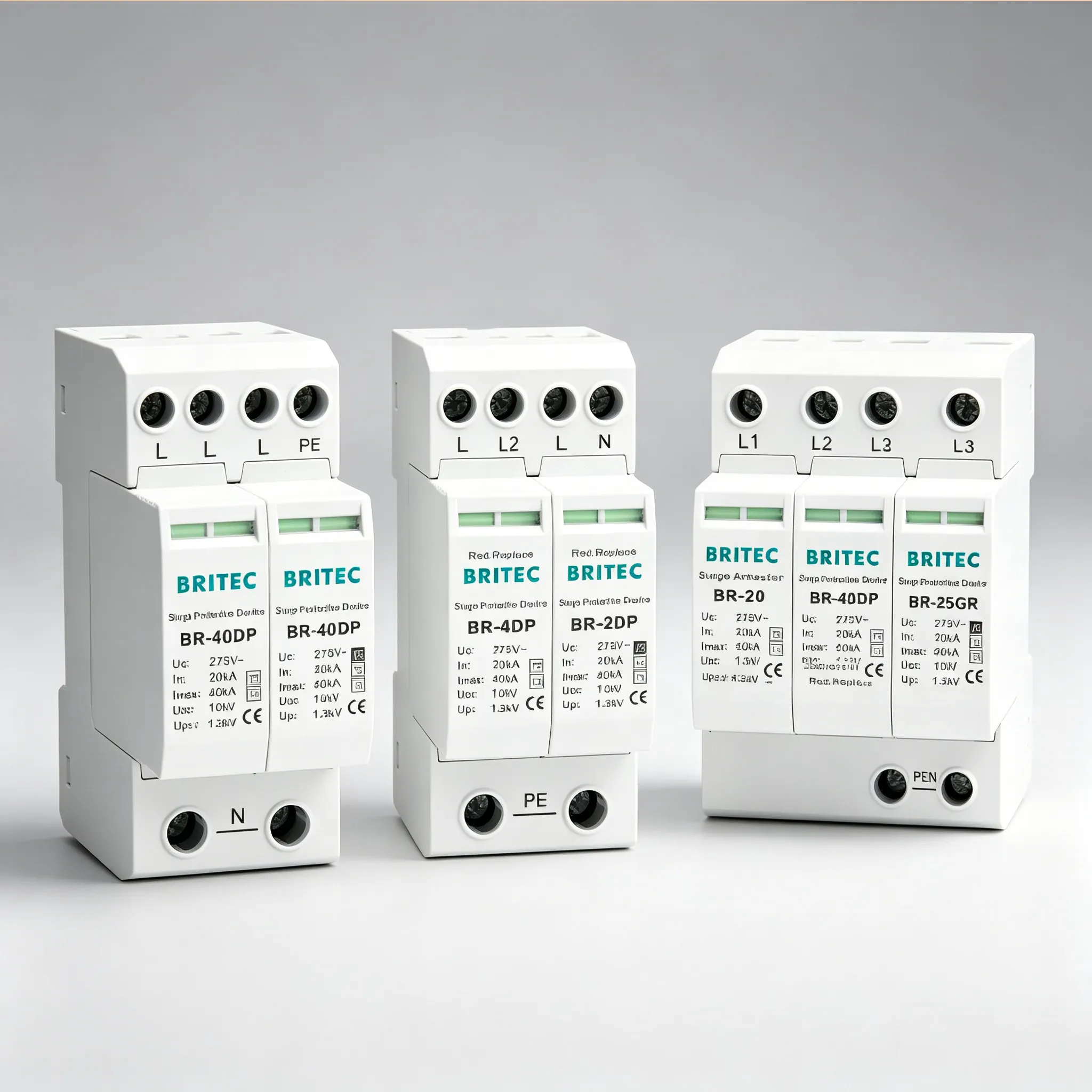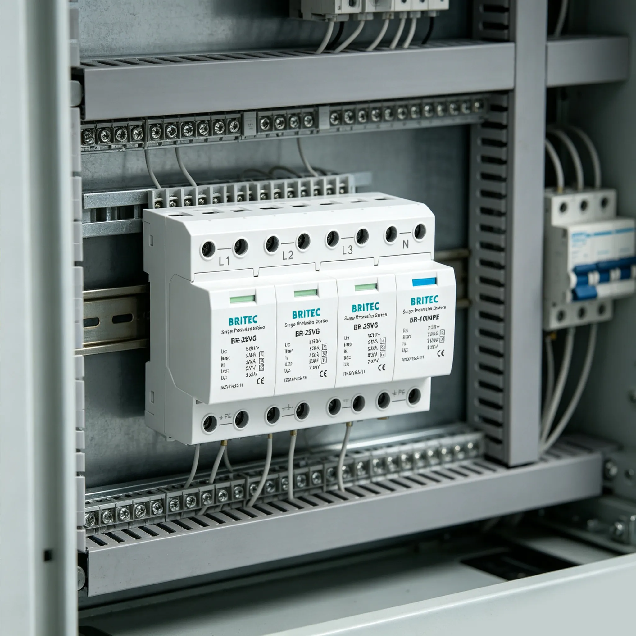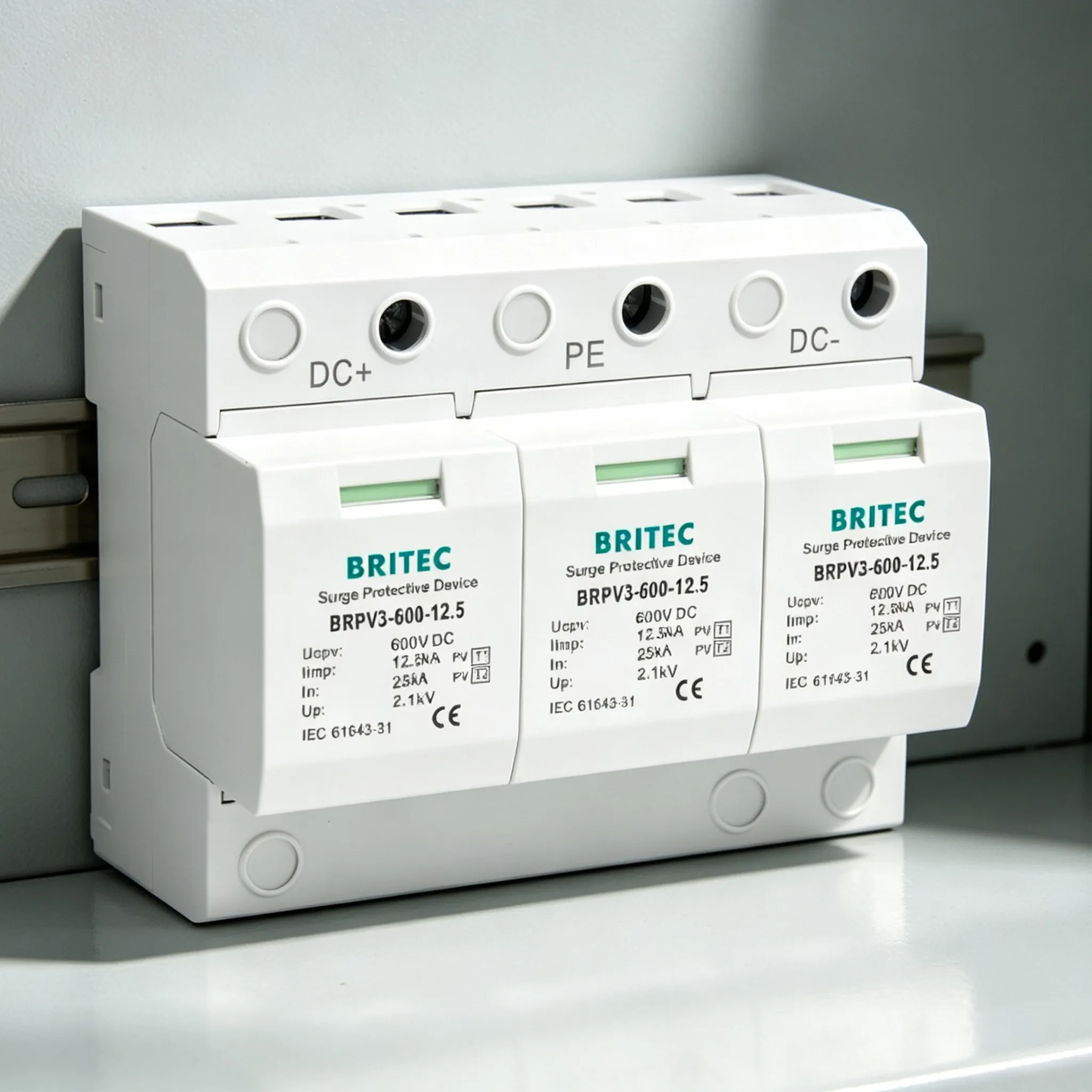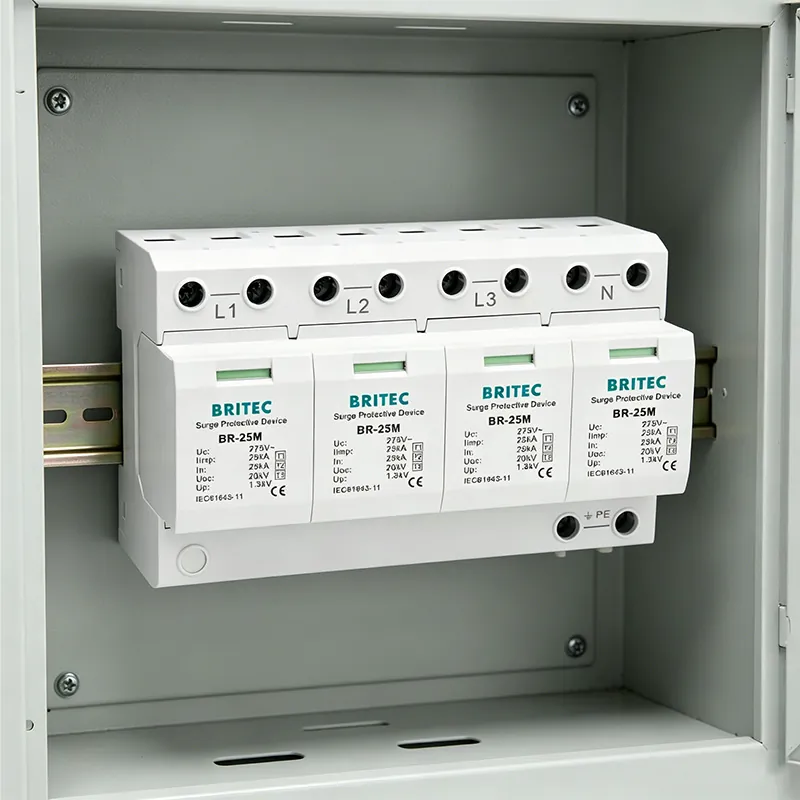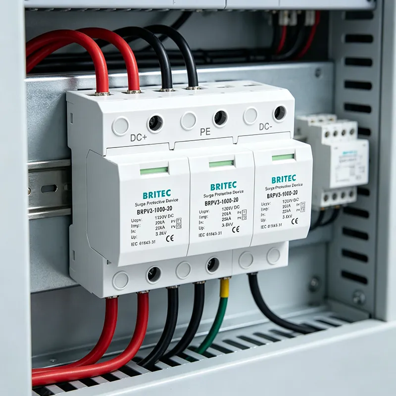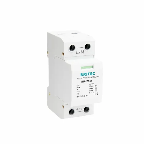

If your facility is located in a region with frequent thunderstorms, the question is not whether you need surge protection, but whether a standard Type 2 SPD is sufficient or whether a 유형 1 서지 보호 장치 is required at the service entrance. The answer depends on three factors defined by IEC 62305 그리고 IEC 61643-11: whether your building has an external lightning protection system, whether power is supplied via overhead lines, and the local lightning density (keraunic level). This guide explains exactly when a Type 1 SPD is mandatory, what happens if you install the wrong type, and how to select the right configuration for your installation. For an overview of all SPD types, see our surge protection device overview.
Protect Your Facility From Direct Lightning Current
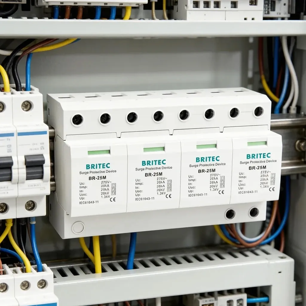
Britec Electric manufactures IEC 61643-11 certified Type 1 SPDs rated at Iimp 25kA (10/350µs), engineered for installations in high-lightning regions worldwide. Our BR-25M series handles partial lightning current at the service entrance, protecting your downstream equipment and Type 2 SPDs from catastrophic failure.
Lightning activity varies dramatically across the globe. The keraunic level (also called thunderstorm days, Td) is the traditional metric: the average number of days per year on which thunder is heard at a given location. According to data from NASA and Vaisala, the global distribution ranges from near zero in polar regions to over 200 days per year in the tropics.
| Region / Country | Keraunic Level (Td) | Lightning Density (flashes/km²/yr) | Type 1 SPD Recommendation |
|---|---|---|---|
| Central Africa (DRC, Cameroon) | 150–200+ | 50–205 | Mandatory |
| Southeast Asia (Singapore, Malaysia, Indonesia) | 150–180 | 20–80 | Mandatory |
| Florida, USA (“Lightning Alley”) | 80–100 | 9–24 | Mandatory |
| Northern Australia (Darwin) | 80 | 15–30 | Mandatory |
| Central Europe (Germany, Austria, Switzerland) | 15–35 | 2–5 | Risk assessment required |
| South America (Brazil, Colombia, Venezuela) | 80–297 (Lake Maracaibo) | 15–233 | Mandatory |
As a practical rule, when the keraunic level exceeds 25 thunderstorm days per year, a formal lightning risk assessment per IEC 62305-2 should be conducted. In regions above 50 Td, a Type 1 SPD at the service entrance is recommended as a baseline, even before completing the full risk calculation.
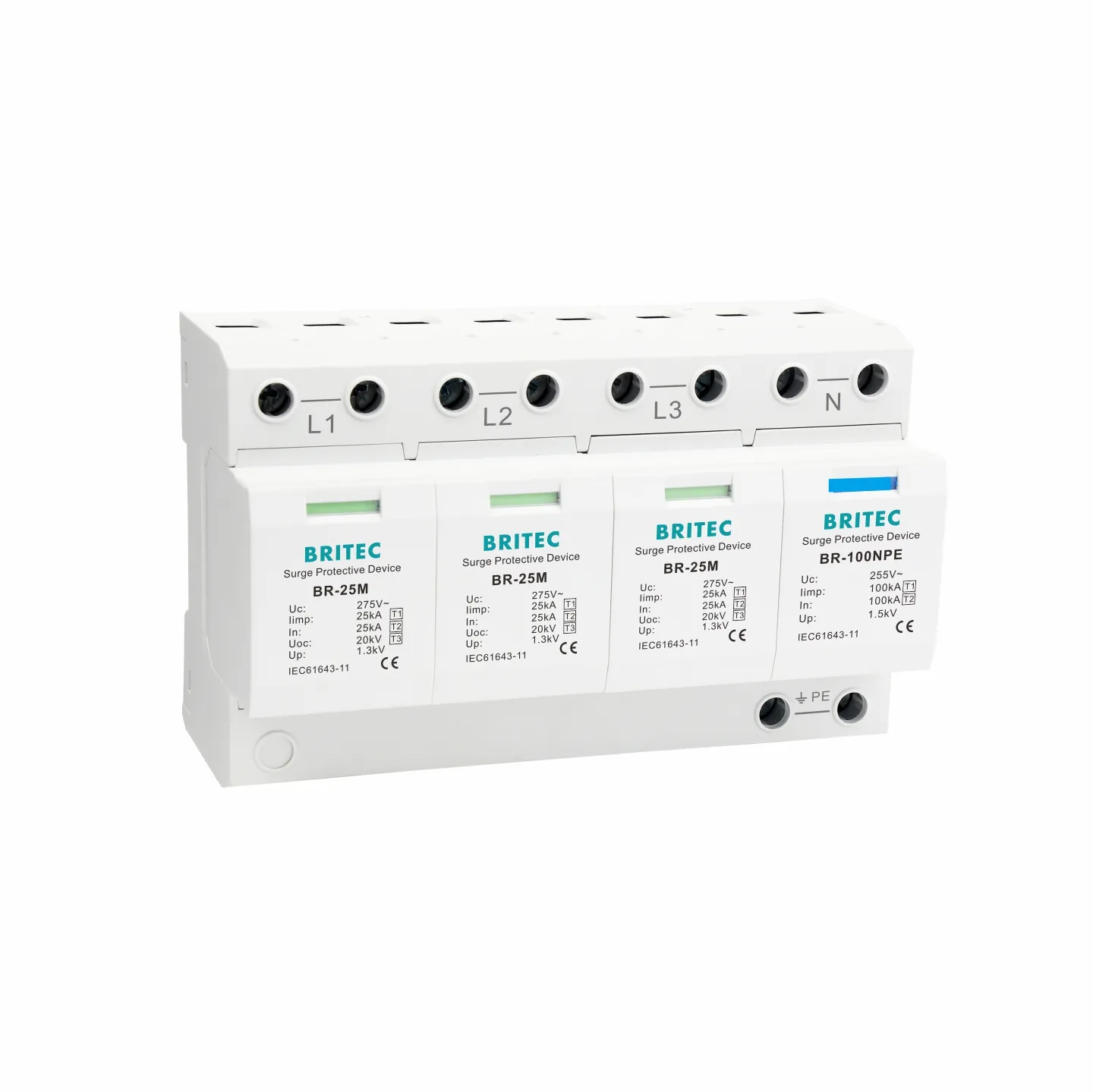
에 따르면 IEC 60364-5-53 그리고 IEC 62305-4, a Type 1 SPD is mandatory at the main distribution board (LPZ 0 → LPZ 1 boundary) under two specific conditions:
When a building is equipped with an external lightning protection system comprising air terminals (lightning rods), down conductors, and an earth termination network per IEC 62305-3, a direct lightning strike to the air terminal will inject partial lightning current into the building’s electrical system through the common earthing network. This partial current has the 10/350 microsecond waveform and can reach tens of kiloamperes. Only a Type 1 SPD certified to IEC 61643-11 Class I can safely discharge this energy to earth without catastrophic failure.
Overhead power lines are directly exposed to lightning. A direct strike to the line, or a nearby strike that induces surge current through electromagnetic coupling, can propagate the 10/350 microsecond lightning waveform into the building’s main distribution board. IEC 60364-5-53 requires a Type 1 SPD at or near the origin of the electrical installation whenever overhead supply lines are present, regardless of whether the building itself has an external LPS.
Key distinction: A building with underground supply and no external LPS may be protected by a Type 2 SPD at the MDB, subject to risk assessment. However, in high-keraunic regions, even underground cables can carry induced lightning current through ground potential rise, making a combined Type 1+2 SPD the safer engineering choice.
The critical technical difference between Type 1 and Type 2 SPDs is the test waveform. IEC 61643-11 defines:
At the same peak current, the 10/350µs waveform delivers 10 to 20 times more total energy than the 8/20µs waveform because of its long duration tail (350 microseconds vs 20 microseconds at the half-value point). When a Type 2 SPD is subjected to 10/350µs current, its MOV elements absorb energy far exceeding their thermal rating, resulting in:
This is why IEC 61643-11 and IEC 62305-4 strictly prohibit substituting a Type 2 SPD for a Type 1 SPD at the LPZ 0 → LPZ 1 boundary.
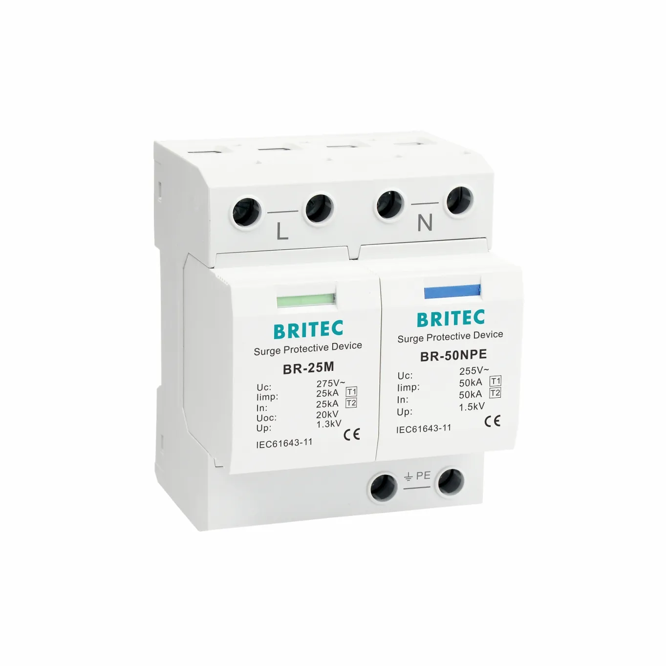
그만큼 브리텍일렉트릭 BR-25M series is engineered for installations in lightning-prone regions. These SPDs are classified as Type 1+2+3 combined devices, certified to IEC 61643-11 and EN 61643-11, with an Iimp of 25kA (10/350µs) and Imax of 120kA (8/20µs).
| 매개 변수 | BR-25M 1P | BR-25M 1+1 | 애플리케이션 |
|---|---|---|---|
| SPD Type (IEC 61643-11) | 클래스 I + II + III | 클래스 I + II + III | Service entrance, LPZ 0→1 |
| Iimp (10/350µs) | 25kA | 25kA (L-N) / 50kA (N-PE) | Partial lightning current |
| Imax (8/20µs) | 120KA | 120KA | Switching surges |
| Uc (275V variant) | 275V | 275V / 255V | 230/400V systems |
| 위로 | 1.3kV 이하 | ≤1.3kV / ≤1.5kV | Below Category IV Uw |
| Earthing system | TN-S, TN-C-S | TT, TN-S | Match to installation |
| Max backup fuse | 200AgG | 200AgG | SCPD coordination |
For single-phase TN-S systems, the BR-25M 1P Type 1 25kA surge arrester provides single-pole L-PE protection. For TT systems or TN-S systems with transformer-side neutral earthing, the BR-25M 1+1 Type 1 25kA for TT and TN-S provides the L-N + N-PE configuration required by IEC 60364-5-53.
Installing a Type 1 SPD alone is not a complete protection strategy. IEC 62305-4 defines a 조정된 SPD 시스템 where multiple SPD types are installed at successive LPZ boundaries to progressively reduce surge voltage to levels that sensitive equipment can withstand.
The standard cascade for lightning-prone regions is:
When a Type 1 and Type 2 SPD are installed in the same system, they must be separated by at least 10 metres of cable between their installation points. If the physical distance is less than 10 metres, install a decoupling coordination inductor between the two positions, or use a combined Type 1+2 device. For detailed guidance on SPD-to-circuit-breaker coordination, see our article on AC SPD single phase coordination with circuit breakers.
Every Type 1 SPD must have an upstream short-circuit protective device (SCPD) to safely disconnect the SPD when its internal MOV reaches end-of-life and fails in short-circuit mode. For the BR-25M series with Iimp 25kA, the maximum permitted backup fuse is 200AgG.
While standard gG fuses or Type C/D MCBs can serve as the SCPD, dedicated SPD backup protectors offer superior coordination. The BRSCB-I-25 Class I 25kA dedicated backup protector is specifically engineered for Type 1 SPD coordination:
For installations using a combined Type 2 SPD with integrated MCB, the BRCB-15/30/40 Type 2 SPD combined with MCB provides a compact all-in-one solution for sub-distribution boards.
The most dangerous and common mistake. In buildings with external LPS or overhead supply, a Type 2 SPD at the service entrance will fail catastrophically during the first significant lightning event, leaving all downstream equipment unprotected.
Many specifiers use the same SPD specification across all project locations. A design adequate for Central Europe (Td 15–35) is insufficient for a project in Southeast Asia (Td 150+). Always check the local keraunic level and conduct an IEC 62305-2 risk assessment.
Installing a 1P SPD in a TT system, or a 1+1 SPD in a TN-C system, creates protection gaps. Verify the earthing system with a qualified electrician before selecting the SPD pole configuration.
IEC 61643-12 requires total SPD lead length (busbar → SPD → PE bar) not to exceed 0.5 metres. Every extra metre adds approximately 1µH of inductance, which at 10kA/µs di/dt adds 10kV of residual voltage, completely negating the SPD’s clamping performance.
SPDs are sacrificial devices. In high-lightning regions, a Type 1 SPD may reach end-of-life within 3–5 years. Without annual visual inspection of the green/red status indicator, a failed SPD can sit unnoticed for years, providing zero protection.
When Type 1 and Type 2 SPDs are installed less than 10 metres apart without a coordination inductor, the faster-responding Type 2 activates first and absorbs more energy than its rating allows, causing premature failure.
Get Expert Guidance on Your Lightning Protection Strategy
Not sure which Type 1 SPD configuration your project needs? Our engineering team helps B2B clients worldwide select the right IEC 61643-11 certified SPDs based on local keraunic levels, earthing systems, and cascade coordination requirements. We also provide dedicated backup protectors and coordination inductors for complete system protection.
A Type 1 SPD is mandatory in two scenarios defined by IEC 60364-5-53 and IEC 62305-4: first, when the building has an external lightning protection system (LPS) with air terminals, down conductors, and an earth termination system; second, when the building is supplied by overhead power lines that can carry direct or nearby lightning strikes into the electrical installation. In both cases, partial lightning current with the 10/350 microsecond waveform can enter the building’s main distribution board, and only a Type 1 SPD tested to IEC 61643-11 Class I can safely discharge this energy.
The fundamental difference is the test waveform. Type 1 SPDs are tested with the 10/350 microsecond lightning impulse current (Iimp), which simulates partial direct lightning current and carries 10 to 20 times more total energy than the 8/20 microsecond waveform used for Type 2 SPDs. Type 1 SPDs install at the LPZ 0 to 1 boundary (main distribution board) to handle lightning current entering the building. Type 2 SPDs install at the LPZ 1 to 2 boundary (sub-distribution boards) to handle switching surges and residual lightning energy. A Type 2 SPD cannot substitute for a Type 1 SPD where Type 1 is required.
There is no single keraunic threshold that automatically mandates a Type 1 SPD, but IEC 62305-2 risk assessment becomes critical when the keraunic level (thunderstorm days per year) exceeds 25. Regions with keraunic levels above 50, such as Florida (80–100 thunderstorm days), Singapore (180 days), and Central Africa (150–200 days), have a high probability of direct or nearby lightning strikes. In these regions, if the building has an external LPS or is supplied by overhead lines, Type 1 SPD installation is effectively mandatory.
No. A Type 2 SPD is tested with the 8/20 microsecond waveform at a nominal discharge current (In) of up to 20kA. The 10/350 microsecond lightning waveform carries significantly more energy because of its long duration tail. When a Type 2 SPD is subjected to 10/350 microsecond current, the MOV elements absorb 10 to 20 times their rated thermal energy, causing immediate catastrophic failure at the exact moment protection is needed most.
Iimp (impulse current) is the peak current value of the 10/350 microsecond test waveform used to certify Type 1 SPDs per IEC 61643-11. It represents the partial lightning current that the SPD must safely discharge to earth. For residential and small commercial installations in lightning-prone regions, Iimp of 12.5kA per pole is the minimum acceptable value. For buildings with external lightning protection systems, IEC 62305-4 typically requires Iimp of at least 25kA per pole at the service entrance.
If your building has no external lightning protection system (LPS) and is supplied exclusively by underground cables, a Type 1 SPD is not strictly mandatory under IEC 60364-5-53. However, in lightning-prone regions with high keraunic levels, a risk assessment per IEC 62305-2 may still recommend a combined Type 1+2 SPD at the main distribution board, because nearby strikes can induce surge currents into underground cables through ground potential rise.
A 1P (single-pole) Type 1 SPD connects between line and protective earth (L-PE) and is used in TN-S and TN-C-S earthing systems. A 1+1 (1P+N) configuration consists of two modules: one between line and neutral (L-N) and one between neutral and earth (N-PE). The 1+1 configuration is required for TT earthing systems and for TN-S systems where the neutral-earth bond is at the transformer. Always match the SPD configuration to your earthing system as verified by a qualified electrician.
Every Type 1 SPD requires an upstream short-circuit protective device (SCPD) to safely disconnect the SPD if its internal MOV fails in short-circuit mode. For Type 1 SPDs with Iimp of 25kA, the maximum permitted backup fuse is typically 200A gG. Dedicated SPD backup protectors such as the Britec BRSCB-I-25 are engineered specifically for lightning impulse coordination, cutting leakage current to under 3A and withstanding 25kA at 10/350 microseconds without nuisance tripping.
Installing only a Type 2 SPD where a Type 1 is required creates a dangerous false sense of security. When lightning current with the 10/350 microsecond waveform enters the installation, the Type 2 SPD will attempt to absorb energy far exceeding its rating. The result is immediate catastrophic failure: the MOV elements can shatter, the SPD housing can rupture, and the protected equipment is left exposed to the full lightning impulse. The cost of upgrading from Type 2 to Type 1+2 is minimal compared to the cost of equipment damage and downtime after a strike.
In lightning-prone regions, Type 1 SPDs should be inspected at least once per year, and immediately after any known direct lightning strike to the building or nearby utility infrastructure. SPDs are sacrificial devices that degrade with each surge event. The thermal disconnection indicator window should be checked visually: green means operational, red means the module has reached end-of-life and must be replaced. In regions with 50 or more thunderstorm days per year, expect module replacement every 3 to 5 years on average.